
Launching vehicle and satellite connection-separation apparatus

a satellite connection and satellite technology, applied in the direction of cosmonautic components, weapons, cosmonautic parts, etc., can solve the problems of reducing reliability, generating high vibratory disturbance or shock along the whole vehicle, and not being the most suitable for joining large structures with cylindrical interfaces, etc., to achieve the effect of improving performance and large mass

Active Publication Date: 2011-04-12
AIRBUS DEFENCE & SPACE
View PDF16 Cites 14 Cited by
  • Summary
  • Abstract
  • Description
  • Claims
  • Application Information

AI Technical Summary

Benefits of technology

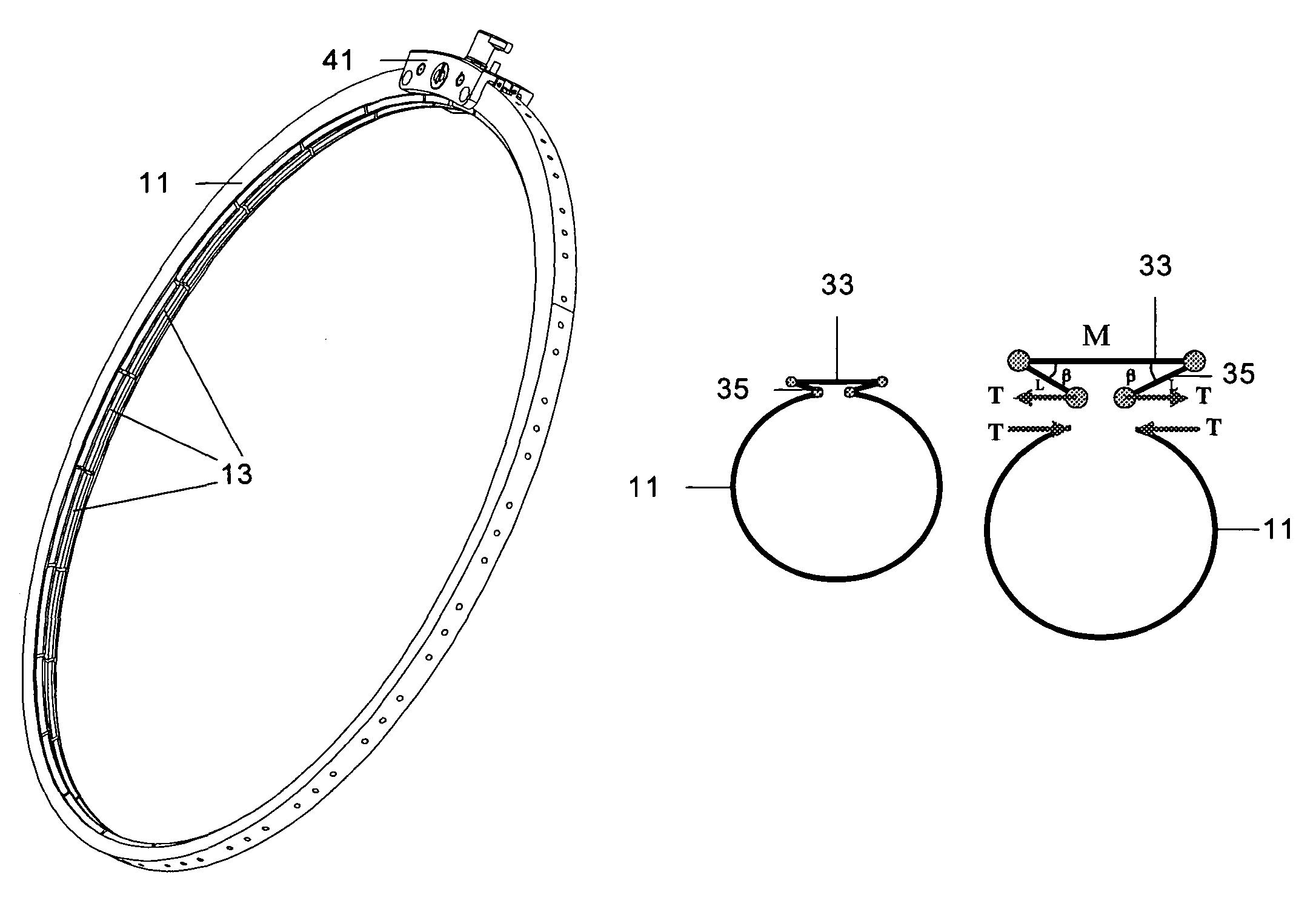
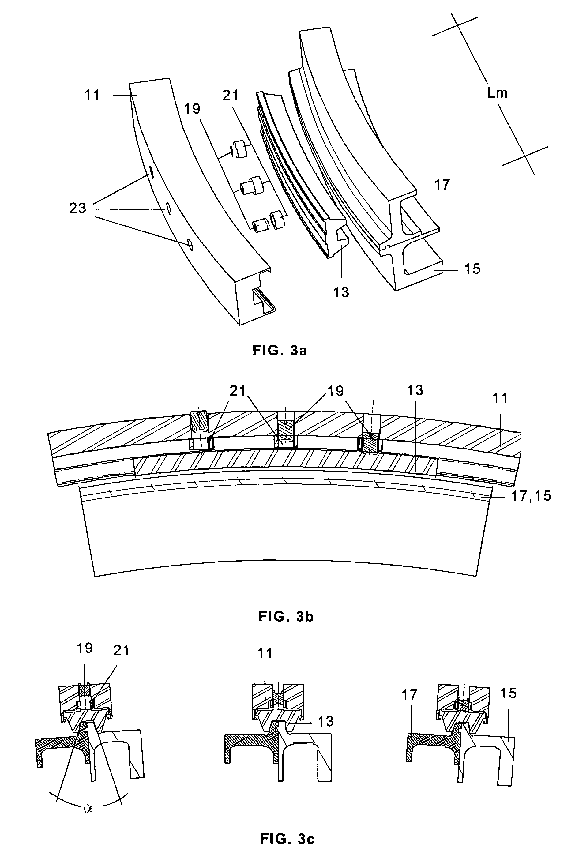
The present invention proposes a launching vehicle and satellite connection-separation apparatus with a controlled opening mechanism that reduces shock during separation. The apparatus includes a band with clamps that are tightened by sliding the clamps in a ring-making interface between the vehicles. The band has a mechanism for controlled opening in two phases to dissipate energy and minimize shock. The apparatus also includes a lever system to reduce the tension to the locking element and reduce the shock transmitted to the satellite. The controlled opening mechanism uses a slow and tangential movement of the band to minimize the residual energy at the time of separation. The apparatus also includes push bars for radially tightening the band-clamps assembly and solving the problem of tightening limitations and performance loss. The invention solves the problem of uncoupling the start-up of the opening-closing mechanism and the band, and improves the advantages of the Huessler mechanism.

Problems solved by technology

Connections based on pyrotechnic strings or explosive bolts are effective and reliable but they generate high levels of vibratory disturbance or shocks which move along the whole vehicle until reaching the most sensitive elements.
These and other similar devices are effective for joining-separating lightweight structures such as antennas or solar panels, but they are not the most adequate for joining large structures with cylindrical interfaces.
In these cases it would be required to arrange in a circle either many of these discrete elements with the resulting reduction in reliability, or few of them with the resulting increase in connection loads.
In contrast, the disadvantage is that this very uniform preload causes elastic deformation, with axial symmetry, of the interface rings which, when suddenly relaxed, transforms into kinetic energy of the elemental masses of those rings, that is, in a vibratory signal of high acceleration at the natural frequency corresponding to that symmetrical mode.
To that end it reduces the two opening spots to one, which translates into a deceleration of the separation speed of the band with respect to the interface rings, remaining in contact for longer before distancing itself from them and consequently delaying the start of free vibration of these rings.
The drawback of this system is the loss of reliability due to its requiring the complete and simultaneous release of the screws in order to ensure the separation of the band from the ring interface.
Furthermore, as the band tension relaxes, the energy available for withdrawing the screw is less and therefore the safety margin for the deployment decreases.
The disadvantage of the system is that it requires the very mechanism in order to perform the tightening.
In fact the mechanism itself is proposed as a tightening system, which makes the starting position of the mechanism have some uncertainty related to the results of commissioning it, which leads to a lack of assurance in performance reproducibility.

Method used


Image

  • Launching vehicle and satellite connection-separation apparatus
  • Launching vehicle and satellite connection-separation apparatus
  • Launching vehicle and satellite connection-separation apparatus

Examples


first embodiment

[0086]FIGS. 6 and 7 show the opening-closing device 41 with the controlled opening mechanism in three positions. The opening device 41 comprises a conventional mechanism 46 for opening-closing of the band 11 including a retaining element such as, for example, a bolt 47 which joins the ends of the band and which may be released at the time of separating the satellite from its launcher by means of for example a pyrotechnic cutter 48, and the controlled opening mechanism is formed by a support 43 connected in an articulated manner to the two ends 7, 9 of the band by means of the connecting rods 45.

[0087]In the first of the positions mentioned, from top to bottom, the starting position is represented, before the command for separating the satellite from the launcher vehicle, with the ends 7, 9 of the band very close together. The second is an intermediate position in which the band 11 has not yet separated from the interface rings 15, 17, but in which its tension has relaxed given that ...

second embodiment

[0089]Following FIGS. 8a and 8b the controlled opening mechanism will now be described.

[0090]The opening-closing device 61 includes in this case a support 63 including two grooves 65 defining the movement that two shafts 67 associated to the ends of the band 11 must follow. The shape and size of the grooves 65 are designed such that they have two sections 68, 69 of different slope and with a transition between them. The first section 68 is defined with a very steep slope in order to slow down the separation movement of the ends of the band 11. The angle formed by this section with a vertical line is a design parameter equivalent to the initial angle of the connecting rod in the first embodiment of the invention. The smaller this angle is the slower the initial separation will be. Kinematic compatibility forces the main support to shift vertically, i.e. outwards, in order to allow the separation of both shafts. For this it is necessary to invest the corresponding kinetic energy, whic...

third embodiment

[0095]the controlled opening mechanism is now described following FIGS. 9a and 9b.

[0096]The opening-closing device 71 includes in this case a support 73 including two grooves 75 which define the movement that two shafts 77 associated to the ends 7, 9 of the band 11 must follow. A nub 80 is disposed between the shafts 77.

[0097]The support 73 has certain elasticity which allows managing the times of two sections similar to those of the previous embodiment. For its part, the opening-closing device 71 contains similar locking and unlocking elements.

[0098]In this case, the support 73 is the only metal part which, due to its elasticity and the presence of a separator 76 in each groove 75, allows two positions 78, 79 of its lower portion. In one of these, that corresponding to its natural position 79 (open position), it leaves a sufficient allowance for the shafts 77 to pass through it. In the other, that corresponding to its deformed position 78 (closed position), this allowance is cance...


PUM


Abstract

A launcher and satellite connection-separation apparatus for launching and satellite vehicles has a band-clamp assembly of a band with an inner channel in which clamps are located in a sliding manner for application to rings interfacing between the vehicles, and a union-separation device on ends of the band for radially tightening the band and controlling opening of the band in first and second phases such that the ends of the band shift in contact with the rings for dissipating by friction elastic energy corresponding to the tightening of the band and separate from the rings until reaching a parking position.

Description

FIELD OF THE INVENTION[0001]The present invention refers to a launching vehicle and satellite connection apparatus which must separate when reaching the suitable altitude, in which the connection is performed by means of a tightened band with a plurality of clamps acting upon the satellite and the launcher interface rings, and in which the separation is carried out by means of an electrically transmitted command which activates the opening mechanism of the band.[0002]More particularly, the present invention refers to a launching vehicle and satellite connection-separation apparatus in which the disturbance caused by the opening of said band is reduced to the minimum.BACKGROUND[0003]Since the beginning of the development of technologies for carrying loads to outer space many connection and separation systems have been developed for the different structures or phases which make up a carry vehicle and particularly for that which joins the latter to its payload or satellite. Connections...

Claims


Application Information

Patent Timeline
Patent Type & Authority Patents(United States)
IPC IPC(8): B64G1/64
CPCB64G1/641B64G1/642B64G1/6425
Inventor LANCHO DONCEL, MIGUEL
Owner AIRBUS DEFENCE & SPACE
Learn More