
Primary panel and motor controller integration for aircraft power distribution system

a technology of aircraft power distribution system and motor controller, which is applied in the direction of energy-efficient board measures, machines/engines, and efficient propulsion technologies, etc., can solve the problems of reducing the efficiency of engine and the resulting thrust of aircraft propulsion, the difficulty of “more electric” aircraft power system residing in the amount of power being moved, and the need for aircraft weight and other issues, to achieve the effect of maximizing space and weight efficiency, and reducing the size of the panel

Active Publication Date: 2011-04-12
HAMILTON SUNDSTRAND CORP
View PDF12 Cites 25 Cited by
  • Summary
  • Abstract
  • Description
  • Claims
  • Application Information

AI Technical Summary

Benefits of technology

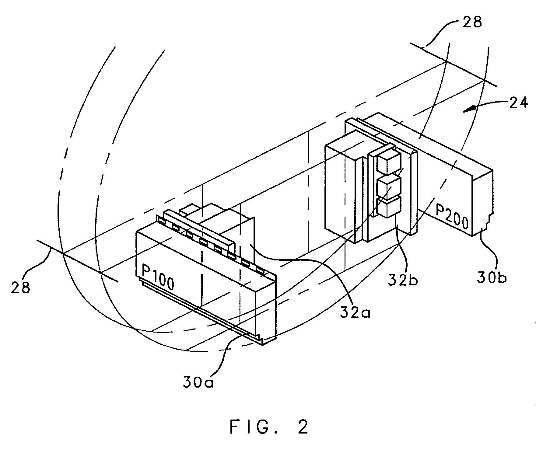
[0011]The primary distribution panel and the HVDC panel may be located back to back within the aft electronics bay to provide for efficient aircraft installation and minimal panel structure for the provided function, achieving an overall lighter combined assembly. Space and weight efficiency is further maximized in the aft electronics bay, as no wire routing volume or protection is required between the panels. This multitude of advantages makes this concept preferred for optimizing aircraft performance.
[0012]The present invention therefore provides an aircraft power distribution system which produces significant weight and power loss reduction while handling increased electrical loads expected of “more electric” aircraft power systems.

Problems solved by technology

Each of these conventional power distributions systems reduces the engine efficiency and the resulting thrust for aircraft propulsion.
A difficulty of the “more electric” aircraft power system resides in the amount of power being moved.
Protective systems increase aircraft weight and are necessary, but directly affect performance in terms of range, fuel burn and operation cost.

Method used


Image

  • Primary panel and motor controller integration for aircraft power distribution system
  • Primary panel and motor controller integration for aircraft power distribution system
  • Primary panel and motor controller integration for aircraft power distribution system

Examples


Embodiment Construction

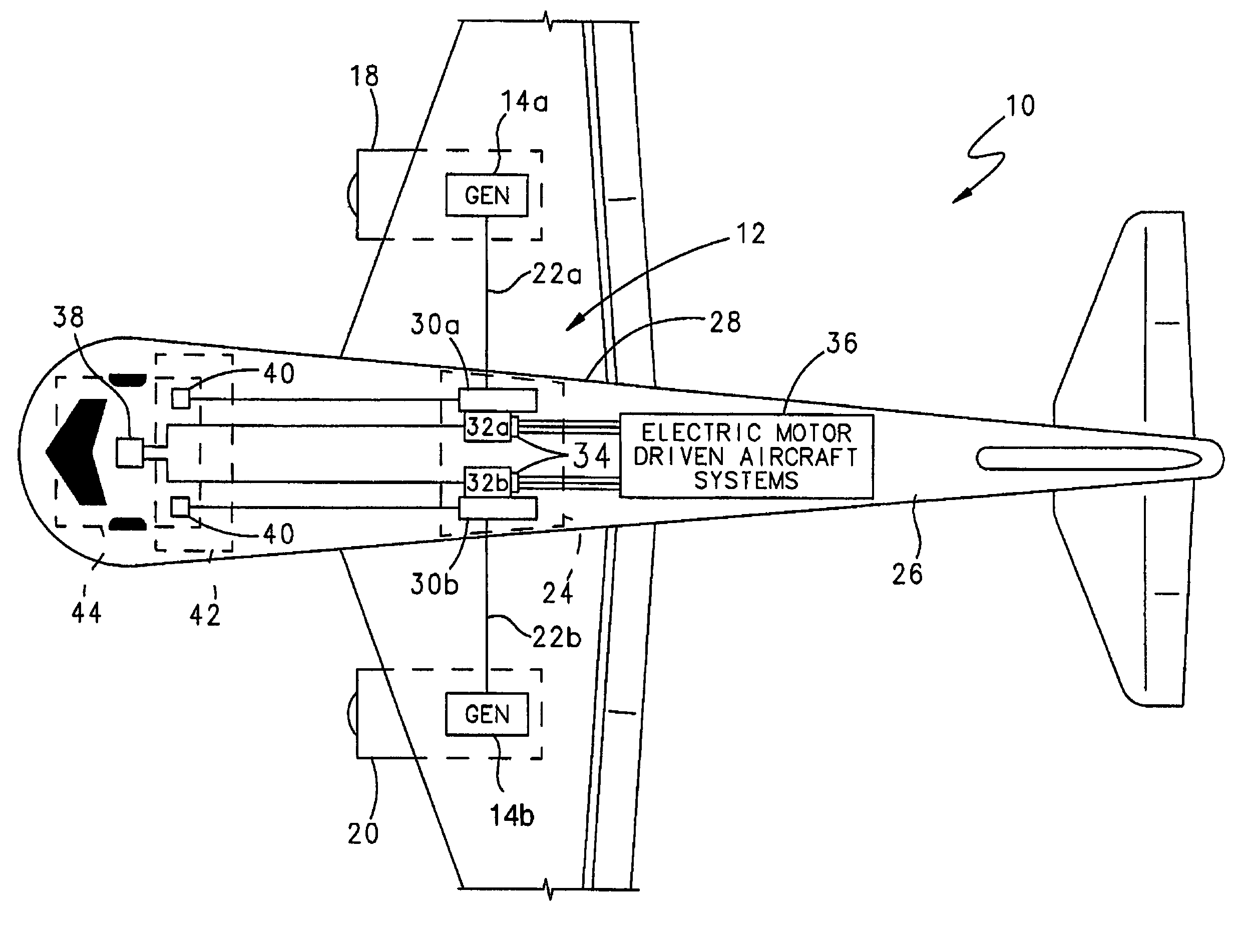
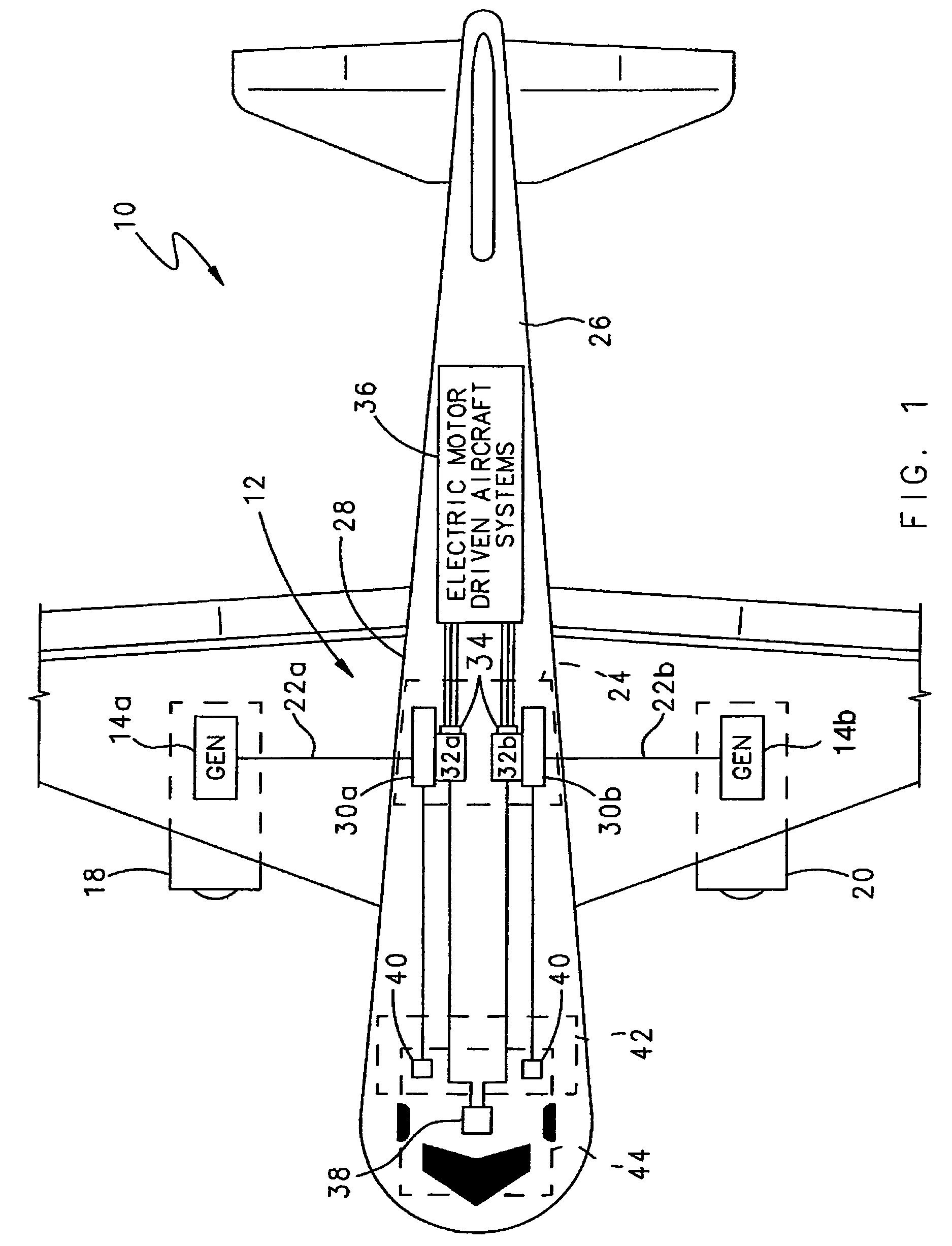
[0017]FIG. 1 illustrates a general schematic plan view of a twin-engine aircraft 10 with an electric power generation and distribution system 12 which is powered by a generator 14a, 14b coupled to and driven from each of the aircraft engines 18, 20. The output of each generator 14a, 14b is coupled by main power feeders 22a, 22b to an electronics bay 24 which is preferably located within the fuselage 26 near a wing root 28. It should be understood that the present invention is equally advantageous for use with aircraft with any number of engines.

[0018]The electric power generation and distribution system 12 preferably includes a primary distribution panel (P100, P200) 30a, 30b which each receives power from one generator 14a, 14b over a respective main power feeder 22a, 22b. That is, the generator 14a, 14b coupled to the aircraft engine 18, communicates with the primary distribution panel (P100) 30a on one side of the aircraft and the generator 14b coupled to the aircraft engine 20 c...


PUM


Abstract

An electric power generation and distribution system includes a primary distribution panel, which preferably operates at 230 VAC, and a High Voltage Direct Current (HVDC) panel in direct electrical communication therewith. The HVDC panels power motor controllers which drive electric motors residing in the center or aft sections of the aircraft. As many of the large electrical loads are located in the aft section of the aircraft, an aft electronics bay is located adjacent the aircraft wing roots to house the primary distribution panels and the HVDC panels.

Description

BACKGROUND OF THE INVENTION[0001]The present invention relates to an aircraft power distribution system, and more particularly to an aircraft power distribution system that combines an alternating current power panel and a high voltage direct current motor controller panel which minimizes power loss from feeder resistance while maximizing weight savings.[0002]Conventional gas turbine powered aircraft provide a variety of power to the aircraft in addition to the thrust required for propulsion. The three main power draws from the engine are electrical, bleed air, and pneumatic / hydraulic. In addition to the engine driven generators that provide electrical power to the aircraft, bleed air is drawn off the engine and used for the aircraft pressurization, cooling and heating systems. The pneumatic / hydraulic systems are pressurized with pumps which are driven by an engine driven gearbox. Each of these conventional power distributions systems reduces the engine efficiency and the resulting ...

Claims


Application Information

Patent Timeline
Patent Type & Authority Patents(United States)
IPC IPC(8): B64D41/00
CPCB64D41/00F02C7/36H02J4/00B64D2221/00Y02T50/545Y02T50/671Y02T50/54Y02T50/44H02J2310/44Y02T50/40Y02T50/50Y02T50/60
Inventor WAVERING, JEFFREY T.CARTER, ERIC A.MAIER, JOSEF
Owner HAMILTON SUNDSTRAND CORP
Learn More