
Self-expanding stent and delivery system

a self-expanding, stent technology, applied in the field of medical appliances, can solve the problems of high concentration of therapeutic agents for the affected part of the body, significant friction between the stent surface and the sheath, and shear force may be especially damaging in relation to the coated se sten

Active Publication Date: 2011-04-05
BOSTON SCI SCIMED INC
View PDF18 Cites 158 Cited by
  • Summary
  • Abstract
  • Description
  • Claims
  • Application Information

AI Technical Summary

Benefits of technology

The patent describes a medical appliance for delivering a self-expanding stent in a body. The appliance includes an outer sheath and an inner sheath with a plurality of extensions. The extensions are biodegradable and detachable from the inner sheath. The extensions may be wires or woven sleeves. The appliance also includes an actuator to move the outer sheath with respect to the inner sheath and the plurality of extensions. The stent may be coated with a bioactive agent and the coating may release the agent during deployment. The method of deployment involves inserting the appliance into a lumen of the body and activating the actuator to move the outer sheath and allow the stent to expand. The appliance and method provide improved control and accuracy during stent deployment.

Problems solved by technology

Additionally, treatment of the afflicted part of the body may require a high concentration of therapeutic agent that may not be achievable by systemic administration.
During deployment and loading of self-expanding (SE) stents, there may be significant friction between the stent surface and the sheath.
These shear forces may be especially damaging in relation to coated SE stents.
As the application of drug eluting (DE) coatings to progressively longer stents occurs, the problems resulting from this frictional interaction may increase.
During stent deployment, the compressive force combined with linear displacement may produce an abrasive, scraping action against the DE coating.
These related problems may be progressively exacerbated as stent lengths increase.
These efforts may be problematic, particularly for the longest stents.
Although feasible, rolling sheaths or membranes may require quite difficult processes to produce and assemble the rolling membrane into the finished delivery system.
A rate of expansion of the self-expanding stent may include a delay.

Method used


Image

  • Self-expanding stent and delivery system
  • Self-expanding stent and delivery system
  • Self-expanding stent and delivery system

Examples


Embodiment Construction

[0043]The drive to exploit the application of drug-eluting coatings to self-expanding stents, and particularly to very long stents (up to 150 mm), has brought a number of challenges. Regarding stent deployment, these problems may be related to the compressive stress reaction exerted by an inside surface of the delivery catheter on the coating by the residual spring energy in the compressed, loaded stent.

[0044]The polymer base of the DE coating may thus be subjected to a continuous compressive force, which during deployment may cause a scuffing and / or abrasive action at the interface of the coating and the catheter. There may also be an increase in the stent deployment force.

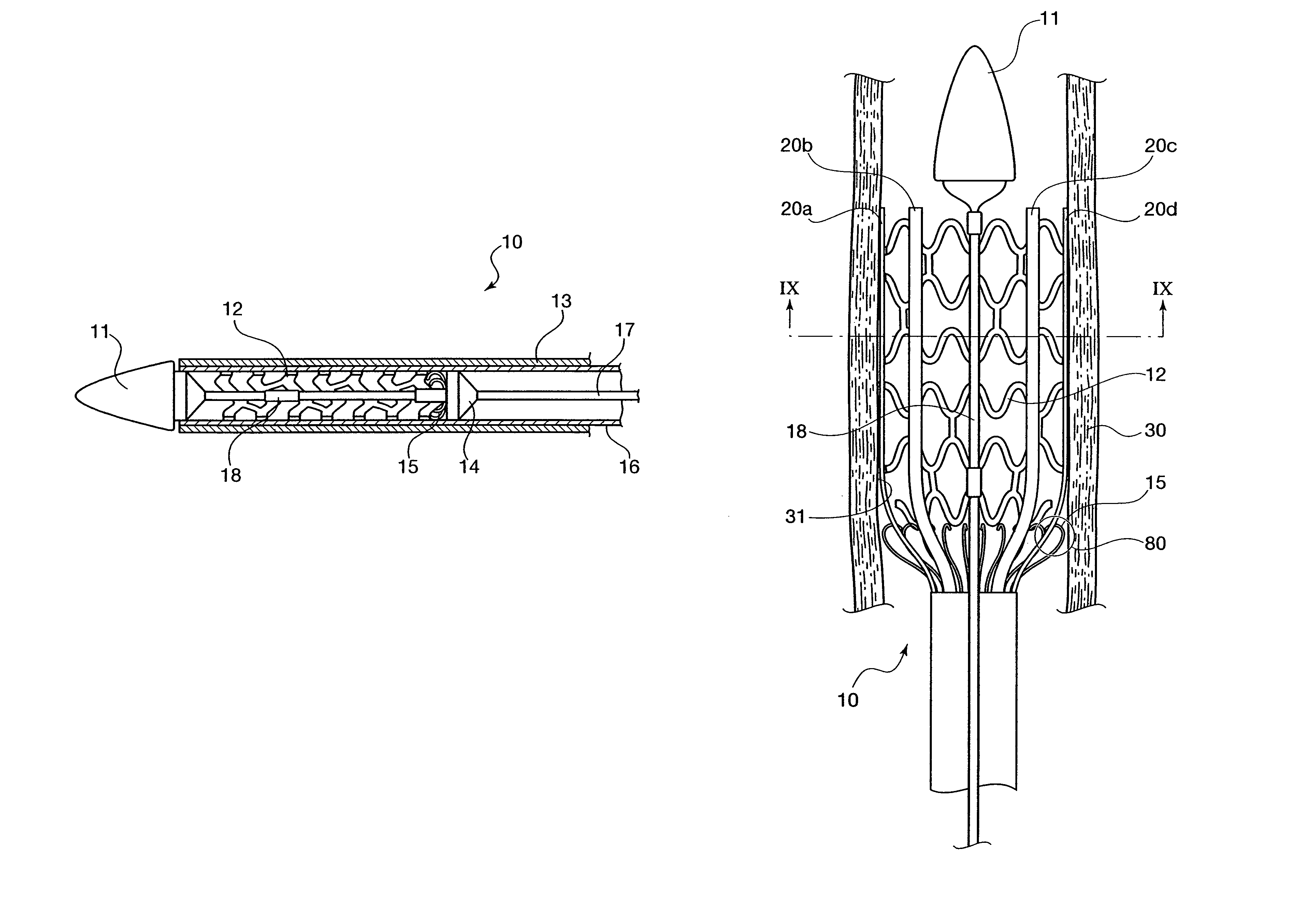
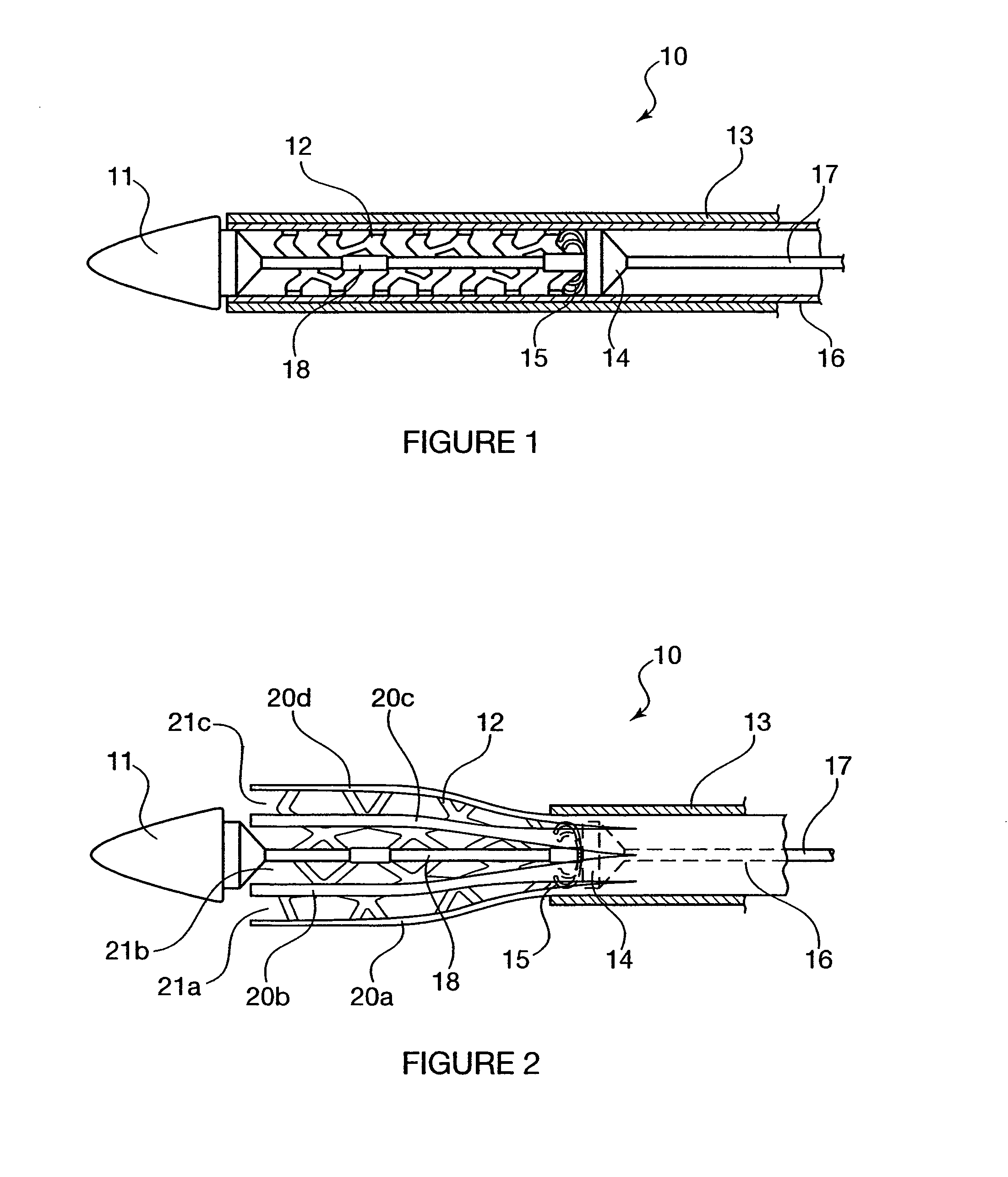
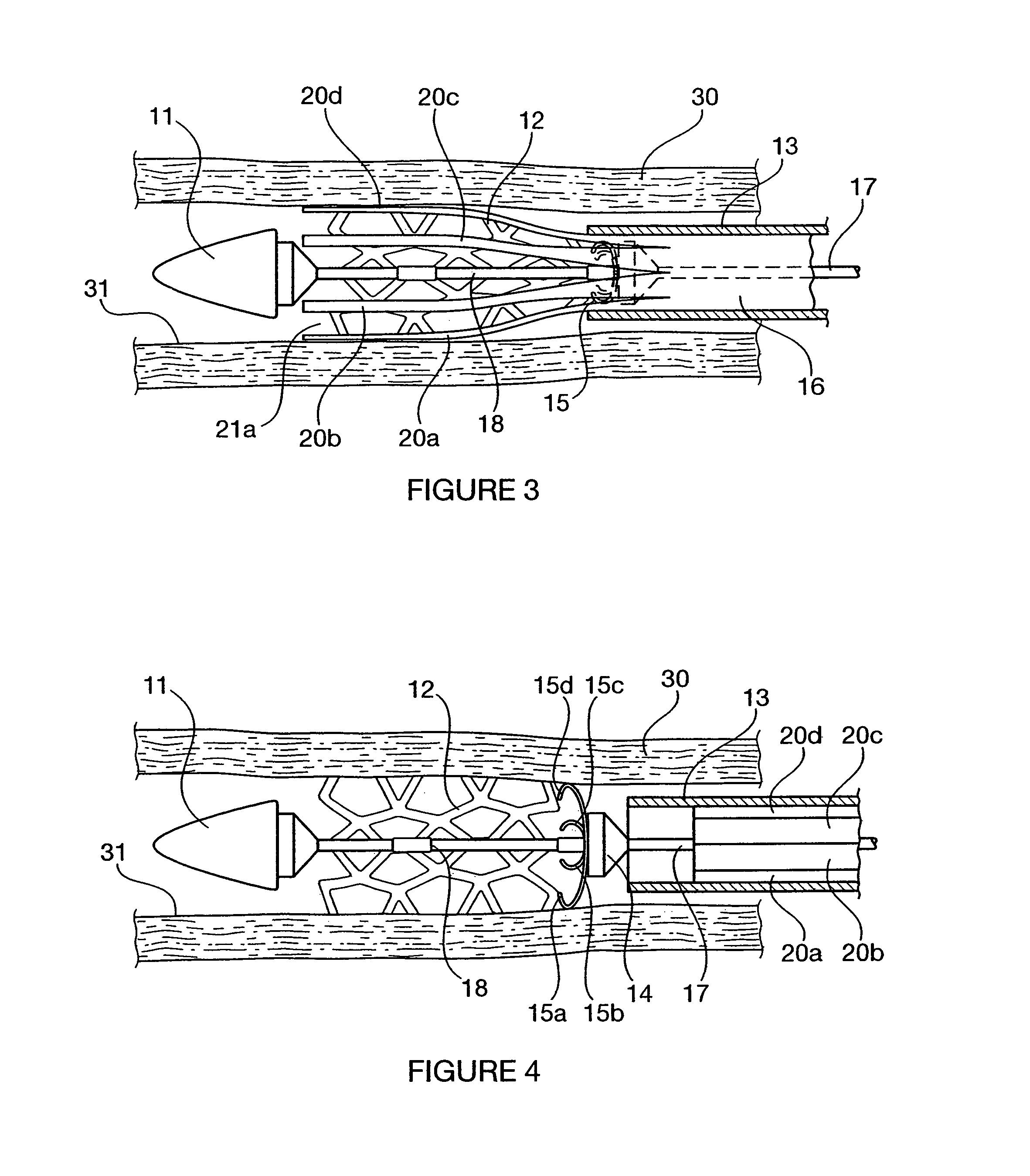
[0045]In an exemplary embodiment of the present invention, an inner sheath (also referred to herein as an inner sleeve) is provided that has a plurality of longitudinal slits. Therefore, the inner sheath may open freely into the body lumen. During deployment, the inner sleeve may then be retracted, followed by th...


PUM

PropertyMeasurementUnit
lengthsaaaaaaaaaa
arc lengthaaaaaaaaaa
diameteraaaaaaaaaa

Abstract

A medical appliance is provided that includes an outer sheath adapted to enclose a self-expanding stent in an inner space before deployment of the self-expanding stent and an inner sheath arranged between the outer sheath and the self-expanding stent before deployment of the self-expanding stent. The inner sheath includes longitudinal slits that extend from a distal end of the medical appliance to the proximal end. The longitudinal slits form a plurality of inner sleeve tails. The medical appliance also includes an actuator adapted to move the outer sheath with respect to the inner sheath during deployment of the self-expanding stent. The actuator is adapted to cause the outer sheath to move proximally. A method of deploying a self-expanding stent is provided. A method of loading a delivery mechanism is provided.

Description

FIELD OF THE INVENTION[0001]The present invention relates to medical appliances. More particularly, the present invention relates to a delivery device for a self-expanding stent, a method of using the delivery system, and a method of producing the system.BACKGROUND INFORMATION[0002]Medical devices may be coated so that the surfaces of such devices have desired properties or effects. For example, it may be useful to coat medical devices to provide for the localized delivery of therapeutic agents to target locations within the body, such as to treat localized disease (e.g., heart disease) or occluded body lumens. Localized drug delivery may avoid some of the problems of systemic drug administration, which may be accompanied by unwanted effects on parts of the body which are not to be treated. Additionally, treatment of the afflicted part of the body may require a high concentration of therapeutic agent that may not be achievable by systemic administration. Localized drug delivery may ...

Claims


Application Information

Patent Timeline
Patent Type & Authority Patents(United States)
IPC IPC(8): A61F2/84
CPCA61F2/95A61F2002/9517A61F2002/9522A61F2210/0004A61F2250/0067A61F2002/9665A61F2/9517A61F2/9522
Inventor AUSTIN, MICHAEL
Owner BOSTON SCI SCIMED INC
Learn More