V-type engine

a v-type engine and valve body technology, applied in the direction of valve drives, machines/engines, mechanical equipment, etc., can solve the problems of difficult to achieve a more compact valve-operating device, and achieve the effect of reducing the distance between the intake and exhaust push rods and improving the durability of the sliding contact portions

Active Publication Date: 2011-04-05
HONDA MOTOR CO LTD
View PDF13 Cites 3 Cited by
  • Summary
  • Abstract
  • Description
  • Claims
  • Application Information

AI Technical Summary

Benefits of technology

[0006]The present invention has been made in view of the above-described circumstances. An object of the present invention is to provide a V-type engine having the following characteristics. Specifically, the V-type engine has a compact valve-operating device achieved by a sufficiently reduced distance between intake and exhaust push rods in each of banks. In addition, in the V-type engine, sliding contact portions of intake and exhaust cam followers with corresponding intake and exhaust cams are sufficiently increased, so that the surface pressure of their sliding contact portions is reduced. As a result, the durability of the sliding contact portions can be improved.
[0008]With the first feature of the present invention, the intake and exhaust rocker arms in each bank are arranged in a substantially inverted-V-shape in the plan view, so that the end portions of the intake and exhaust rocker arms on the side of the corresponding intake and exhaust push rods are positioned adjacent to each other. Since the intake and exhaust push rods are positioned adjacent to each other, the first and second intake cam followers and the first and second exhaust cam followers can be arranged adjacent to one another on the intermediate portion of a single cam follower shaft. Further, in conjunction with the arrangement of the cam followers, the intake and exhaust cams can be arranged adjacent to each other. As a result, it is possible to achieve a compact valve-operating device, and eventually a compact V-type engine.
[0009]Moreover, in the first and second intake cam followers, their boss portions abut against each other side by side on the cam follower shaft, while their slipper portions have end portions at one end along the axial direction of the camshaft protrude respectively in opposite directions to each other in such a manner that the slipper portions face each other across the intake cam located therebetween. In addition, in the first and second exhaust cam followers, their boss portions abut against each other side by side on the cam follower shaft, while their slipper portions have end portions at one end along the axial direction of the camshaft protrude respectively in opposite directions to each other in such a manner that the slipper portions face each other across the exhaust cam located therebetween. Accordingly, the intake and exhaust cam, and the first intake and exhaust cam followers as well as the second intake and exhaust cam followers can be concentratedly arranged on the single camshaft and the single cam follower shaft. This makes it possible to achieve the compact valve-operating device, and in particular, to shorten the camshaft. Furthermore, the following effect is provided by the structure in which, in each of the pair of the first and second intake cam followers as well as the pair of the first and second exhaust cam followers, the slipper portions, which are positioned respectively on the opposite sides of the corresponding cam, have the end portions at one end along the axial direction of the camshaft protrude respectively in opposite directions to each other in such a manner that the slipper portions face each other across. Specifically, it is possible to sufficiently secure the sliding contact portions of the intake and exhaust cam followers with the intake and exhaust cams without interfering with the reduction in size of the valve-operating device. As a result, the surface pressure of each of the sliding contact portions is sufficiently reduced, so that the durability of the sliding contact portions can be improved.
[0011]With the second feature of the present invention, it is possible to achieve a further compact valve-operating device, and also to effectively lubricate the periphery of the intake and exhaust cams with lubricating oil dispersed from around the crankpin during the crankshaft rotation.
[0013]With the third feature of the present invention, it is possible to provide the following effect in association with the structure of the first and second exhaust cam followers in which their boss portions abut against each other side by side on the cam follower shaft, and in which their slipper portions have end portions at one end along the axial direction of the camshaft protrude respectively in opposite directions to each other in such a manner that the slipper portions face each other across the exhaust cam located therebetween. Specifically, at the operating position of the decompressing member, only slight protrusion of a tip end portion of the decompressing arm toward the exhaust cam makes it possible to provide very slight lift to the first and second exhaust cam followers by bringing the tip end portion substantially evenly in sliding contact with the first and second exhaust cam followers. In this regard, since the tip end portion of the decompressing arm protrudes by only a small length toward the exhaust cam, it is possible to achieve a compact single decompressing device shared by both the banks, and also to improve the durability of the exhaust cam and the exhaust cam followers while minimizing a reduction in the effective area of the base surface of the exhaust cam due to the formation of the flat portion.
[0014]Furthermore, the flat portion is formed on the camshaft so as to extend from the general surface of the camshaft to the base surface of the exhaust cam, while the decompressing arm of the decompressing member, which is supported around an axis on the flat portion, is caused to protrude toward the base surface of the exhaust cam when the V-type engine is stopped or started. This structure eliminates the need to cause the slipper portions of the exhaust cam followers to protrude outward of the exhaust cam. As a result, it is possible to achieve the decompressing operation performed at the time of start of the V-type engine while maintaining the compactness of the valve-operating device.

Problems solved by technology

In the conventional V-type engine, the distance between intake and exhaust push rods in each bank is increased in association with the V-shape arrangement of intake and exhaust valves in each bank, thus resulting in a difficulty of achieving a more compact valve-operating device.

Method used


Image

  • V-type engine
  • V-type engine
  • V-type engine

Examples


Embodiment Construction

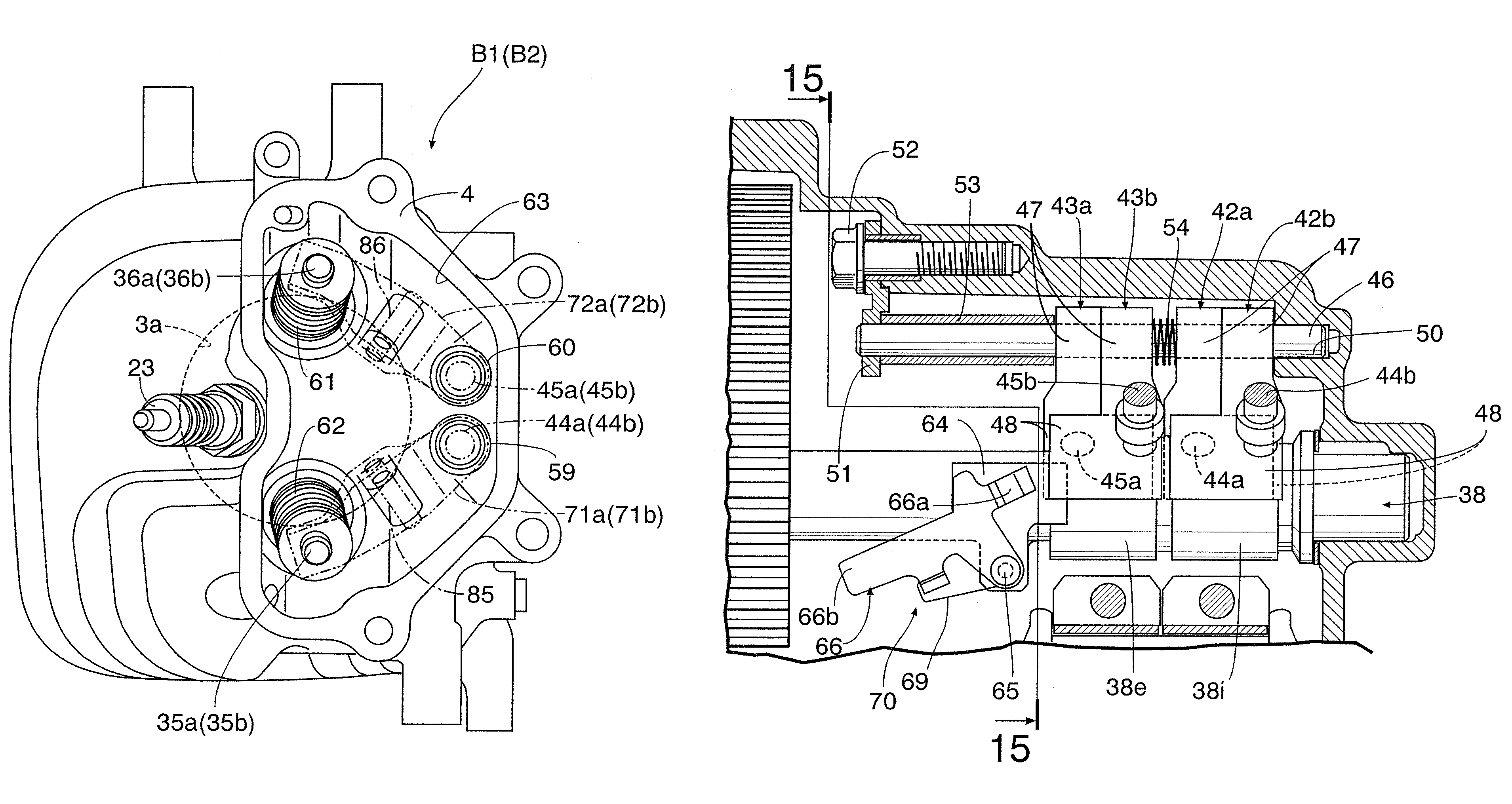
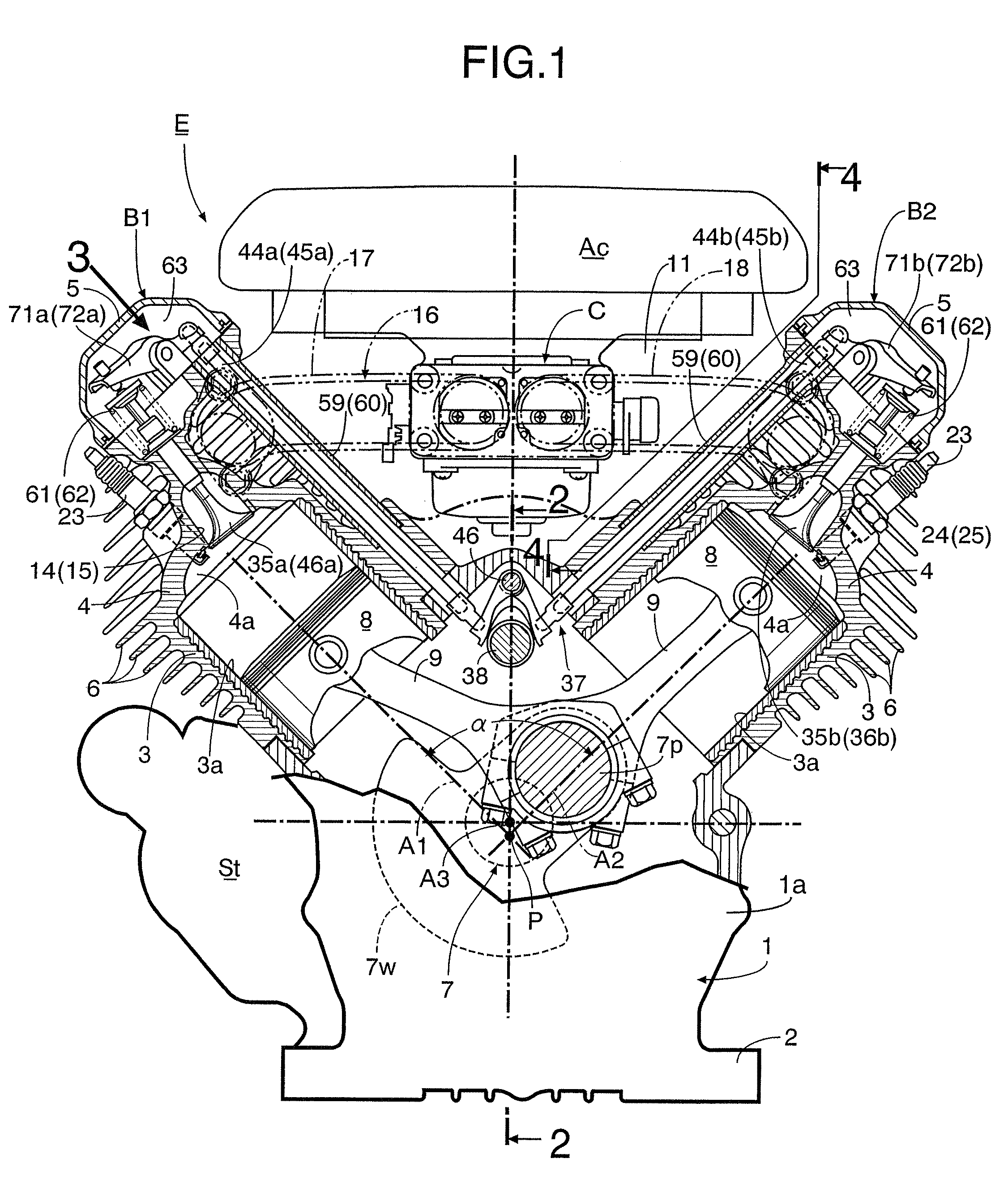
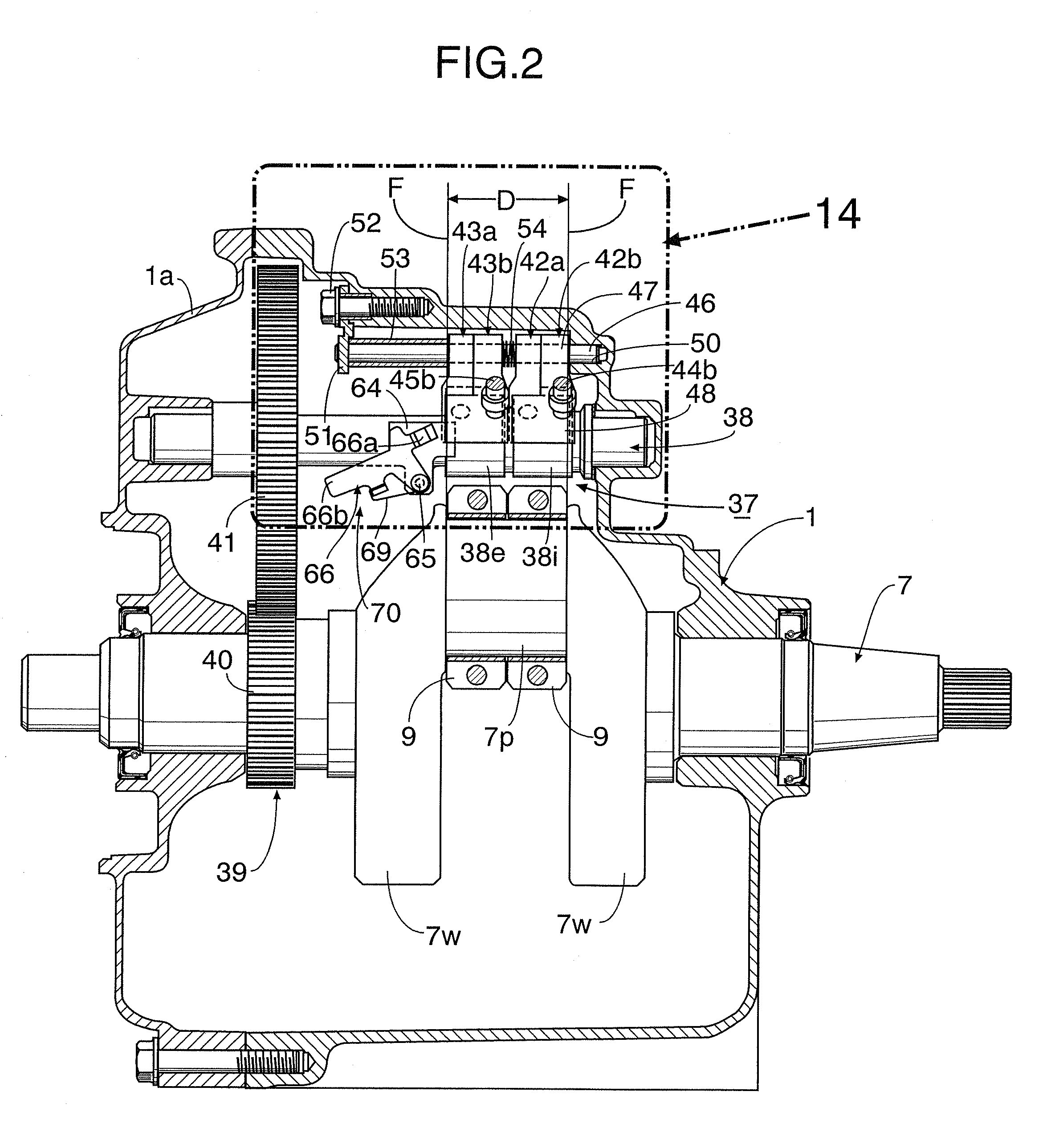
[0031]An embodiment of the present invention will be described below with reference to the accompanying drawings.

[0032]Firstly, as shown in FIGS. 1 to 3, the air-cooled general-purpose V-type engine includes: a crankcase 1; a first bank B1 and a second bank B2 which are arranged respectively on the left and right sides in a V-shape, and which are connected to an upper portion of the crankcase 1; an installation flange 2 formed in a bottom portion of the crankcase 1; and a starter device St provided in one side portion of the crankcase so as to be housed in a space below the first bank B1.

[0033]Each of the first and second banks B1 and B2 includes: a cylinder block 3 which has a cylinder bore 3a, and which is bolt-coupled to the crankcase 1; a cylinder head 4 which has a combustion chamber 4a leading to the cylinder bore 3a, and which is integrally connected to the cylinder block 3; and a head cover 5 bolt-coupled to an end surface of the cylinder head 4. Each of the first and second...


PUM


Abstract

In a V-type engine, intake and exhaust rocker arms in each bank are arranged in a substantially inverted-V-shape in a plan view, so that side end portions of corresponding intake and exhaust push rods are positioned adjacent to each other. Slipper portions of first and second intake cam followers have end portions at one end along the axial direction of a camshaft protrude respectively in opposite directions to each other so that they face each other across an intake cam therebetween. Slipper portions of first and second exhaust cam followers have end portions at one end along the axial direction of the camshaft protrude respectively in opposite directions to each other so that they face each other across an exhaust cam therebetween. This reduces the distance between the push rods in each bank to provide a compact valve-operating device.

Description

BACKGROUND OF THE INVENTION[0001]1. Field of the Invention[0002]The present invention relates to a V-type engine comprising: first and second banks each of which includes a cylinder bore therein, and which are arranged in a V-shape so as to define a valley portion therebetween; a crankcase with which the first and second banks are continuously formed; a crankshaft supported by the crankcase; a cooling fin which protrudes on an outer wall of each of the banks; intake and exhaust valves which are arranged in a V-shape in a head portion of each of the banks; and a valve-operating device which drives the intake and exhaust valves to be opened and closed, the valve-operating device including: a camshaft being disposed above the crankshaft and driven by the crankshaft, first intake and exhaust cam followers and second intake and exhaust cam followers being moved up and down by intake and exhaust cams of the camshaft, respectively, first intake and exhaust push rods and second intake and e...

Claims


Application Information

Patent Timeline
Patent Type & Authority Patents(United States)
IPC IPC(8): F01L1/02F02B75/22
CPCF01L1/146F01L13/085F01L1/182F01L3/00F01L2001/054F01L2800/03F02F1/002F02F1/06F02F7/0012F01L2303/00
Inventor HASHIMOTO, MANABUITO, KEITA
Owner HONDA MOTOR CO LTD
Why Eureka
Try Eureka