Packing board for electronic device, packing board manufacturing method, semiconductor module, semiconductor module manufacturing method, and mobile device
a technology for electronic devices and manufacturing methods, applied in semiconductor devices, semiconductor/solid-state device details, electrical apparatus, etc., can solve the problems of reducing the reliability of the semiconductor device, and reducing the size reduction by narrowing the gap between electrodes. the effect of improving the reliability of the semiconductor modul
- Summary
- Abstract
- Description
- Claims
- Application Information
AI Technical Summary
Benefits of technology
Problems solved by technology
Method used
Image
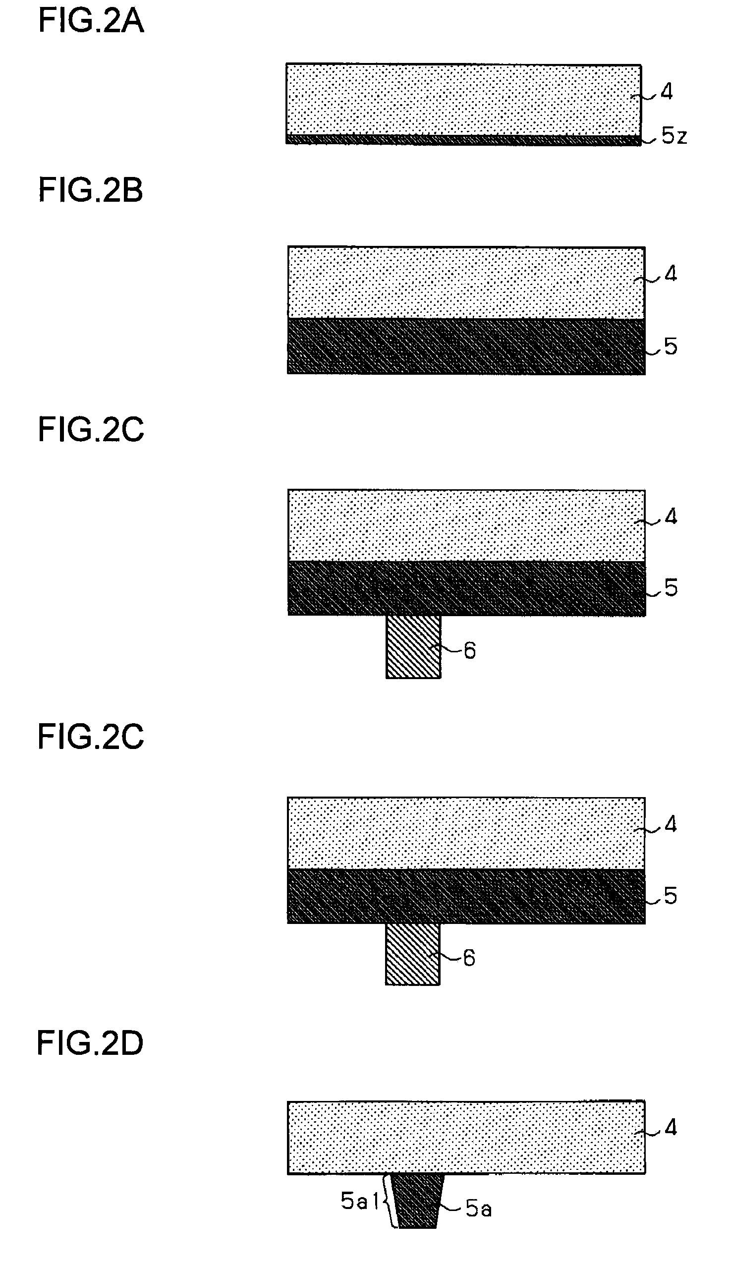
Examples
first embodiment
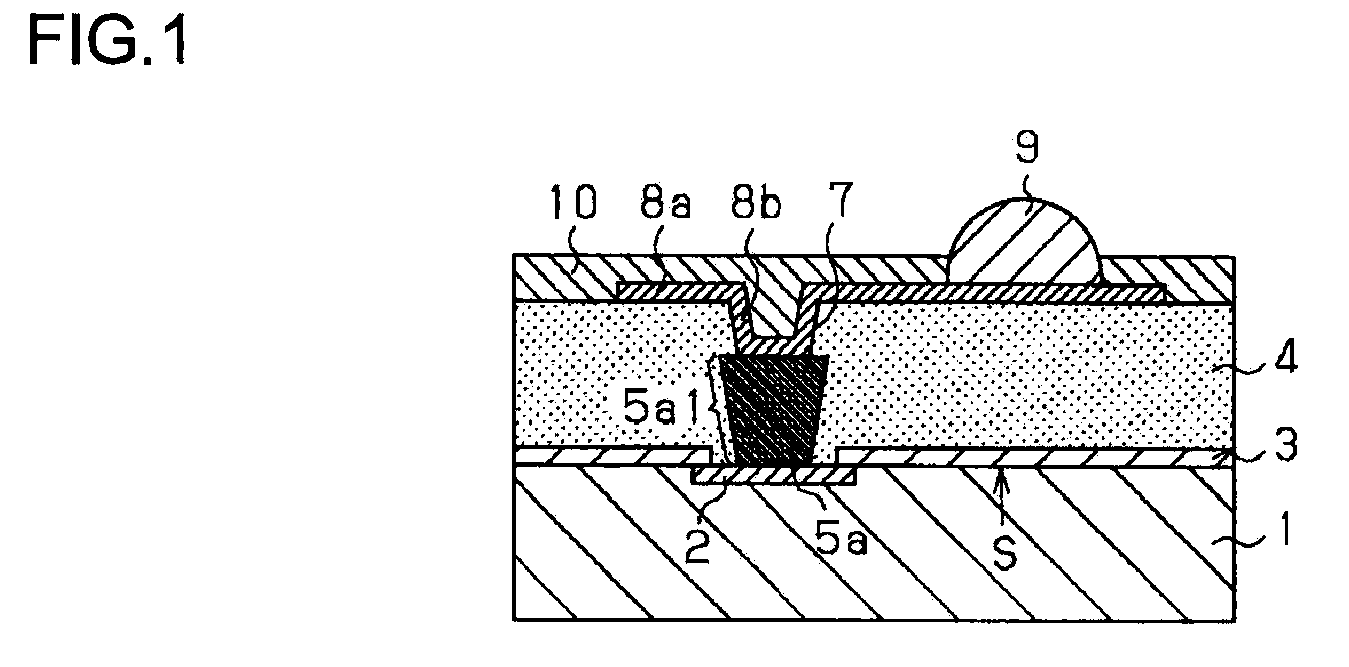
[0036]FIG. 1 is a schematic section showing the structure of a semiconductor module according to the first embodiment. A description will now be given of the semiconductor module according to the first embodiment with reference to FIG. 1.
[0037]A semiconductor substrate 1 is embodied by, for example, a p-type silicon substrate. A semiconductor device (not shown) is formed on the upper surface S (mounting surface) thereof by using a well-known technology. An electrode 2 for the semiconductor device is formed on the surface S (particularly, the periphery thereof). A protective film 3 is formed on at least a part of the surface of the semiconductor substrate 1 so as to expose a certain region of the electrode 2. In order to secure a large gap between the electrodes 2 on the surface S of the semiconductor substrate 1, an insulating layer 4 is formed on the electrode 2 and the protective film 3, and a rewiring pattern 8a is formed on the layer 4. Connection between the electrode 2 and the...
second embodiment
[0063]FIG. 4 is a schematic section showing the structure of a semiconductor module according to the second embodiment. A difference from the first embodiment is that a conductive bump 5b is formed to have a side part 5b1 which is progressively smaller in diameter (dimension) toward the via contact 8b and away from the electrode 2, i.e., the side part 5b1 which is progressively larger in diameter (dimension) toward the electrode 2 and away from the via contact 8b. The other aspects of the second embodiment are the same as the corresponding aspects of the first embodiment.
[0064]More specifically, the conductive bump 5b comprises a metal such as copper (Cu) and embedded in the insulating layer 4 so as to be in contact with the exposed surface of the electrode 2. The height of the conductive bump 5b is about 50 μm. The conductive bump 5b is formed as an inverted truncated cone having an inverted trapezoidal cross section, and is provided with an end part parallel with the contact surfa...
third embodiment
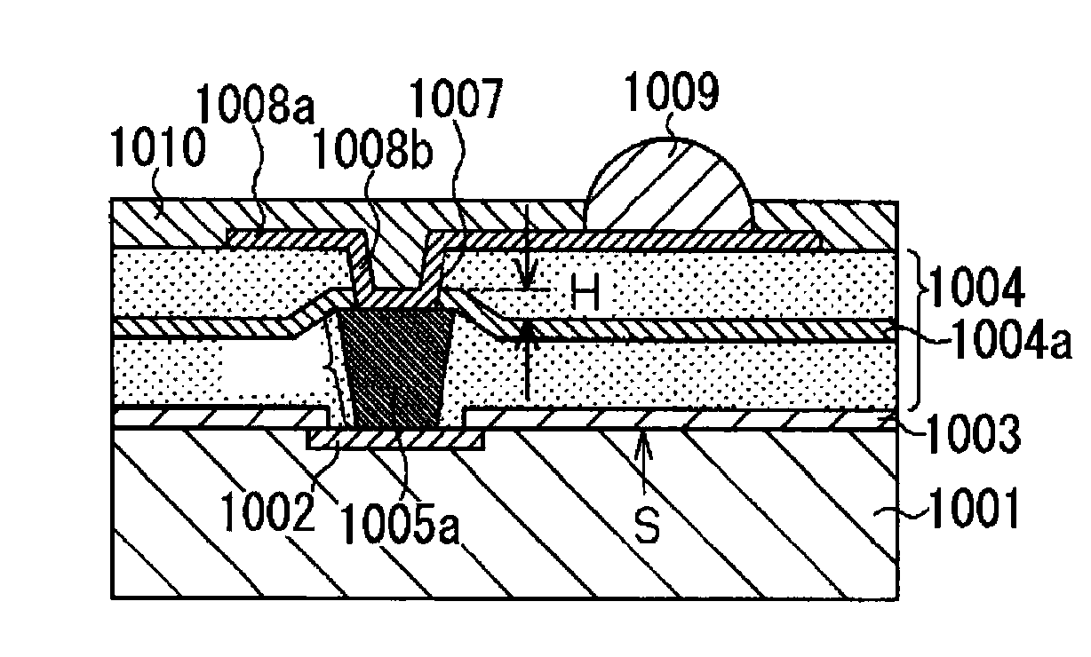
[0081]Recently, with the miniaturization and high performance of electronic appliances, there is a demand for reduction of the size of semiconductor modules used in electronic appliances. To achieve this, narrow-gap electrodes for external connection of semiconductor modules are essential. However, efforts for size reduction by narrowing the gap between electrodes have been successful only to a limited degree due to the constraints imposed by the size of solder bumps and solder bridges produced. Recently, there are attempts to relocate the electrodes by routing lines in a semiconductor module in an effort to overcome the limitation. For relocation, a metal plate may be half-etched so that a resultant projection is used as an electrode or a via, a semiconductor module may be mounted on the metal plate via an insulating layer of, for example, epoxy resin, and the electrode for external connection for the semiconductor module may be connected to the projection.
[0082]For improvement of ...
PUM
 Abstract
Description
Claims
Application Information
 - R&D
- Intellectual Property
- Life Sciences
- Materials
- Tech Scout
- Unparalleled Data Quality
- Higher Quality Content
- 60% Fewer Hallucinations
Browse by: Latest US Patents, China's latest patents, Technical Efficacy Thesaurus, Application Domain, Technology Topic, Popular Technical Reports.
© 2025 PatSnap. All rights reserved.Legal|Privacy policy|Modern Slavery Act Transparency Statement|Sitemap|About US| Contact US: help@patsnap.com


