
Phased array antenna system with two dimensional scanning

a phased array antenna and two-dimensional scanning technology, applied in particular array feeding systems, antennas, electrical equipment, etc., can solve the problems of increasing antenna design complexity and expense, undesirable variable phase shifters in numbers comparable with antenna elements, and not scaling up straightforwardly to two dimensions. , to achieve the effect of avoiding cross-coupling

Inactive Publication Date: 2011-03-22
FLIR BELGIUM BVBA
View PDF17 Cites 5 Cited by
  • Summary
  • Abstract
  • Description
  • Claims
  • Application Information

AI Technical Summary

Benefits of technology

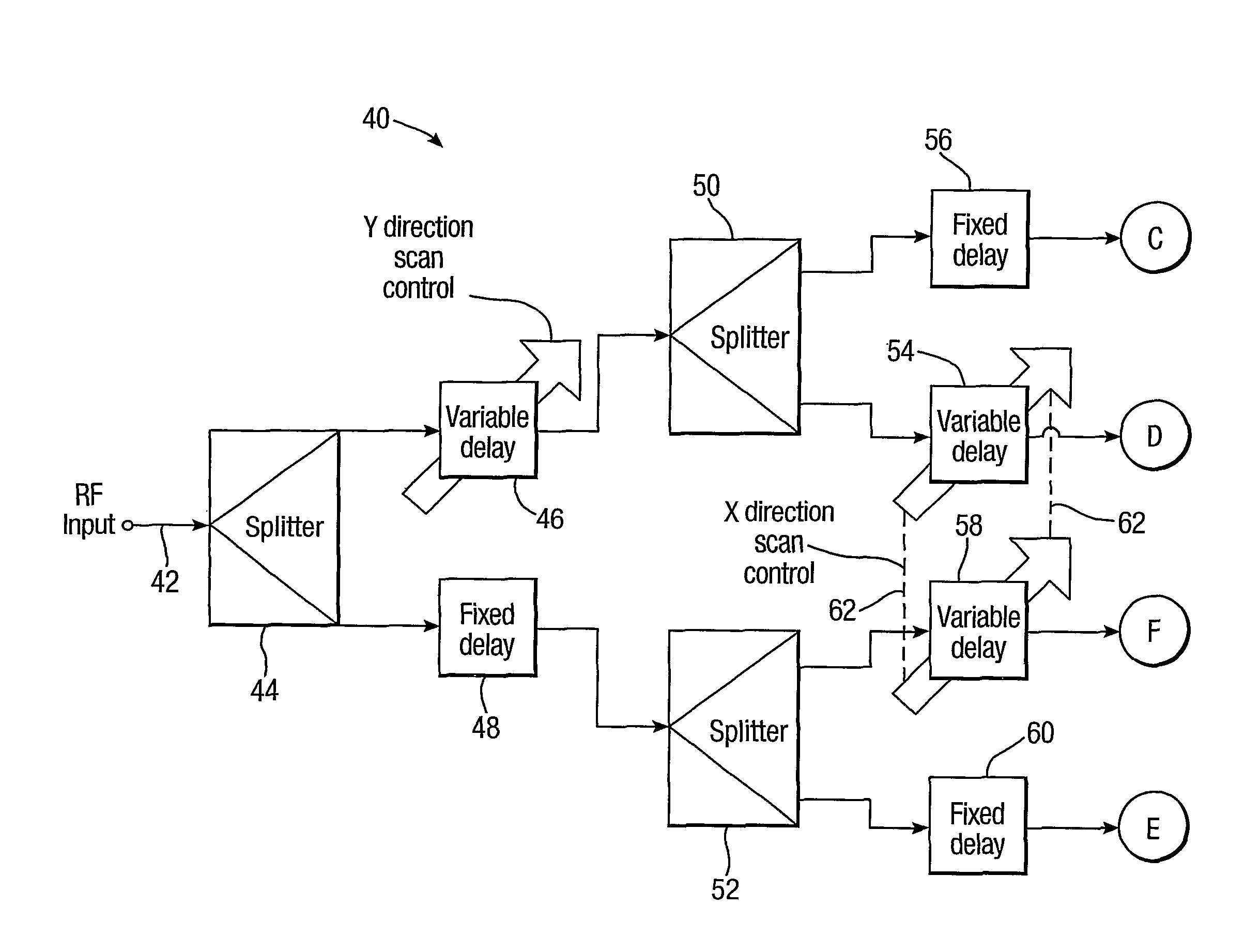
[0022]In one embodiment of a system of the invention having corporate feed networks each with two inputs, the phase difference control means arranged in this way avoids cross-coupling between control of scanning in different dimensions. Here cross-coupling means that an angle of deflection of an antenna beam in one dimension is altered when an angle of deflection in another dimension is changed by scan control.

Problems solved by technology

The use of variable phase shifters in numbers comparable with antenna elements is undesirable, because it greatly increases antenna design complexity and expense.
However, these do not scale up straightforwardly to two dimensions: for a two dimensional array of antenna elements arranged in rows and columns, using one of these prior art solutions per row or column permits scanning of all rows or columns in one dimension, but not scanning in another (orthogonal) dimension.

Method used


Image

  • Phased array antenna system with two dimensional scanning
  • Phased array antenna system with two dimensional scanning
  • Phased array antenna system with two dimensional scanning

Examples


Embodiment Construction

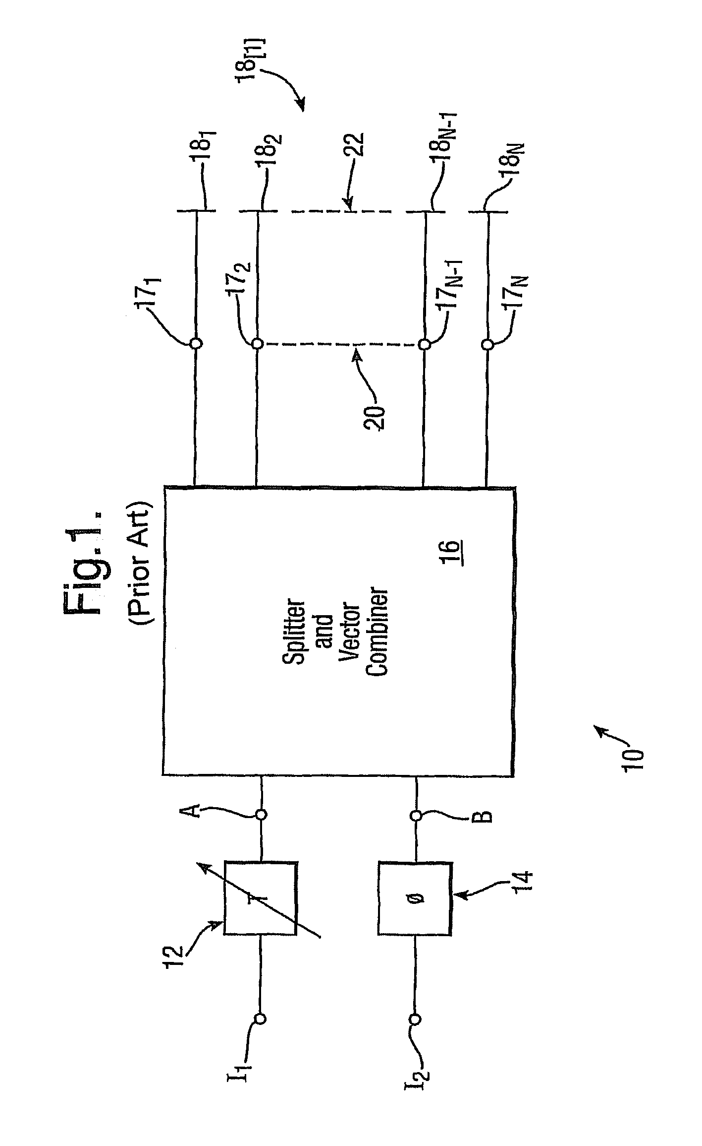
[0072]Referring to FIG. 1, a prior art phased array antenna scanning circuit is illustrated schematically and indicated generally by 10. The circuit 10 is a generalised version of an equivalent disclosed in WO 2004 / 102739: it has two inputs I1 and I2 connected respectively to a variable delay or variable phase shifter 12 and a fixed delay or phase shifter 14, which are in turn both connected respectively to inputs A and B of a splitter and vector combiner unit 16 having output terminals 171 to 17N. The splitter and vector combiner unit 16 is referred to in the art of phased array antennas as a corporate feed network for an antenna array. The circuit 10 has a one dimensional antenna array 18[1] consisting of a line of antenna elements 181 to 18N, which are connected to the output terminals 171 to 17N respectively: here N represents any number of output terminals 171 etc. and antenna elements 181 etc., and dotted lines 20 and 22 indicate that these outputs and antenna elements may be ...


PUM


Abstract

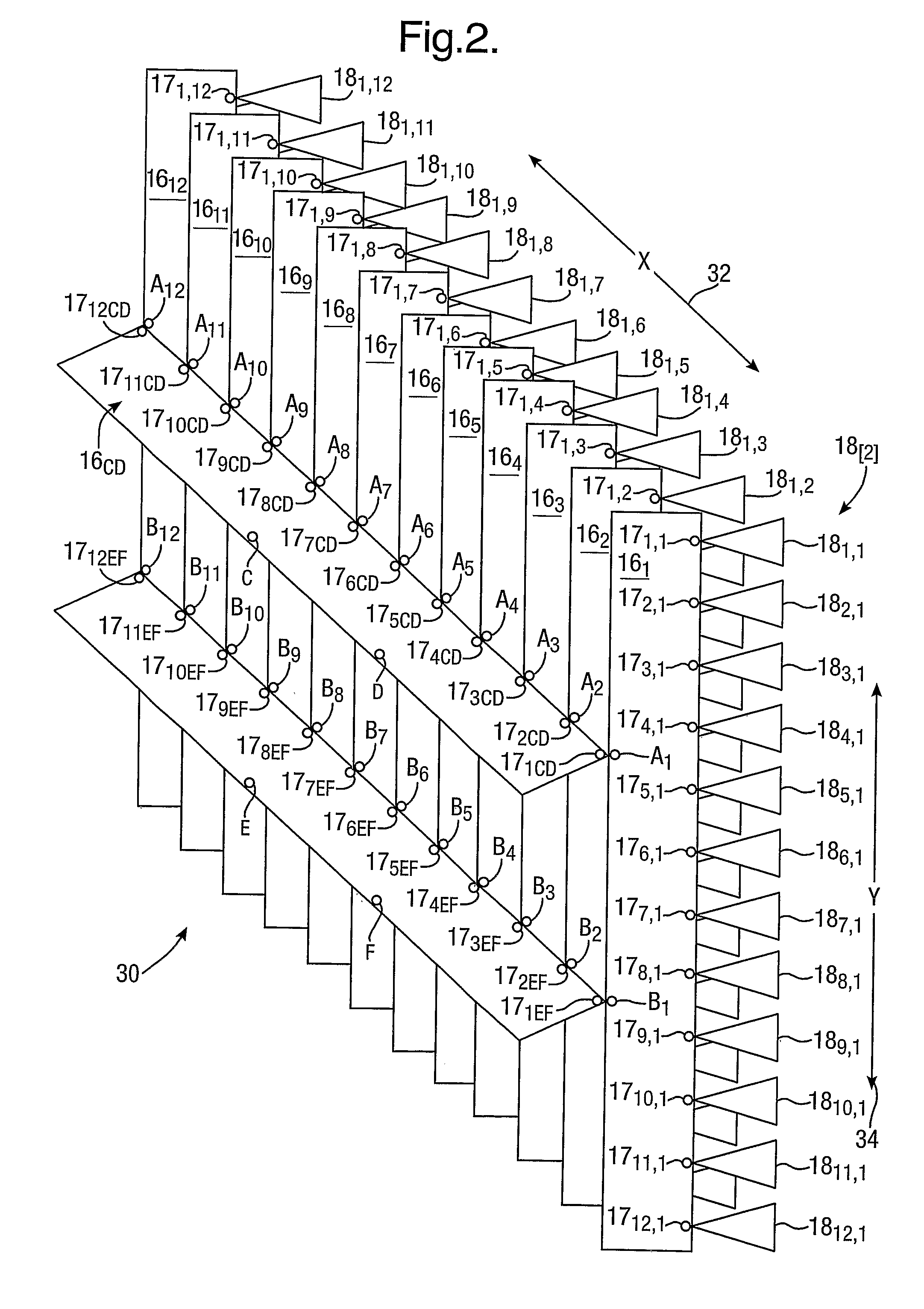
A phased array antenna system with two dimensional scanning includes a two dimensional array A of antenna elements A1,1 to A12,12 arranged in lines; each line is associated with a respective first rank corporate feed network 161 to 1612 having outputs 171,1 to 1712,12 connected to respective antenna elements A1,1 to A12,12 and inputs for variable relative phase input signals. These corporate feed networks each have first and second inputs A1 / B1 to A12 / B12 connected respectively to outputs 171 CD / 1712CD to 171EF / 1712EF of different second rank corporate feed networks 16CD and 16EF. The corporate feed networks 161 to 16EF convert input signals of variable relative phase into relatively greater numbers of output signals for a phased array. The system (30) includes a phase varying circuit 40 for varying phase differences between input signals to each second rank corporate feed network 16CD or 16EF and between input signals to different second rank corporate feed networks 16CD and 16EF to provide control of antenna beam direction in two dimensions.

Description

BACKGROUND OF THE INVENTION[0001](1) Field of the Invention[0002]The present invention relates to a phased array antenna system with two dimensional scanning. It is suitable for use in all areas of technology employing scanning phased array antennas, e.g. radar, television and radio broadcasting and telecommunications, mobile cellular radio (“mobile telephones”) in particular.[0003](2) Description of the Art[0004]Phased array antennas are well known: the subject is discussed in detail in for example a standard textbook well known in the art of antennas, “Microwave Scanning Antennas”, R. C. Hansen, Vol 3 Array Systems, Academic Press, NY, 1966. Such an antenna comprises an array of individual antenna elements (usually eight or more) such as dipoles or patches. The antenna has a radiation pattern incorporating a main lobe or beam and side lobes. The centre of the main lobe is the antenna's direction of maximum sensitivity in receive mode and the direction of its main output radiation ...

Claims


Application Information

Patent Timeline
Patent Type & Authority Patents(United States)
IPC IPC(8): H01Q3/34
CPCH01Q3/36H01Q21/0006H01Q21/061
Inventor HASKELL, PHILIP EDWARD
Owner FLIR BELGIUM BVBA
Learn More