Bar clip applicator

a technology of bar clip and applicator, which is applied in the field of system and method of attaching and aligning reinforcing bars, can solve the problems of increased labor costs, increased labor costs, and increased user fatigue, and achieves the effect of efficient positioning of the bar clip, rapid determination, selection and installation

Active Publication Date: 2011-03-22
DAYTON SUPERIOR CORP
View PDF60 Cites 11 Cited by
  • Summary
  • Abstract
  • Description
  • Claims
  • Application Information

AI Technical Summary

Benefits of technology

[0005]One shortcoming of these two current art plastic clips is the necessity of hand manipulation of a clip and a bar during the application of a clip to a bar by the user. This disadvantage of the current art can contribute to prolonged construction times, higher labor costs and user fatigue. Another shortcoming is the necessity of the user being in very close physical proximity to the application site on a bar in order to apply a clip. This is a disadvantage in complex frameworks where there is typically little room for a user to maneuver himself within the framework of reinforcement bars to reach the application site. This second disadvantage of the current art can also contribute to prolonged construction times, higher labor costs and user fatigue.
[0006]What is needed, then, is a bar clip applicator system that applies a reinforcement bar clip onto a reinforcing bar without the need of manipulating the clip onto the bar by hand. To make the task of attaching reinforcement bars in a framework as quick and easy as possible, it would be advantageous if the bar clip applicator system also provided for application of a bar clip to a reinforcement bar from a stand-off distance. It would also be advantageous if the bar clip applicator system provided for easily recognizable coding means for matching the size of the bar clip, the bar clip applicator and the reinforcement bars.BRIEF SUMMARY OF THE INVENTION
[0008]In a preferred embodiment, the applicator body includes a receiver channel adapted to retain a receiver tip sized in its tip width to be inserted in the upper clasp of a bar clip and to hold the bar clip in place by friction fit. The detachable handle is selected for such length that allows the user to efficiently position the bar clip upon a reinforcement bar and to withdraw the applicator from the bar clip once it is attached, the first clasp assembly holding a first reinforcement bar.
[0009]Advantageously, the bar clip applicator system is formed of selectable and replaceable components that provide the user the ability to rapidly determine, select and install: a bar clip of the required gauge, a receiver tip of the corresponding gauge and a applicator handle the desired length so as to allow the user to remotely apply a bar clip to a reinforcement bar.
[0012]It is an additional object of the present invention to provide a reinforcement bar clip that is removably attachable to a receiver tip of a bar clip applicator and that can be used to attach adjacent reinforcing bars arranged in a framework.

Problems solved by technology

However, both means are labor intensive and, thus, more expensive when compared to the use of more recently developed reinforcing bar clips.
Padrum does not teach an apparatus or method of applying the clip to the reinforcing bars and it is expected that the clips are applied by hand operations with the user in close proximity to the reinforcing bars.
Dragone does not teach an apparatus or method of applying the clip to the reinforcing bars and it is expected that the clips are also applied by hand operations with the user in close proximity to the reinforcing bars.
This disadvantage of the current art can contribute to prolonged construction times, higher labor costs and user fatigue.
This is a disadvantage in complex frameworks where there is typically little room for a user to maneuver himself within the framework of reinforcement bars to reach the application site.
This second disadvantage of the current art can also contribute to prolonged construction times, higher labor costs and user fatigue.

Method used


Image

  • Bar clip applicator
  • Bar clip applicator
  • Bar clip applicator

Examples


Embodiment Construction

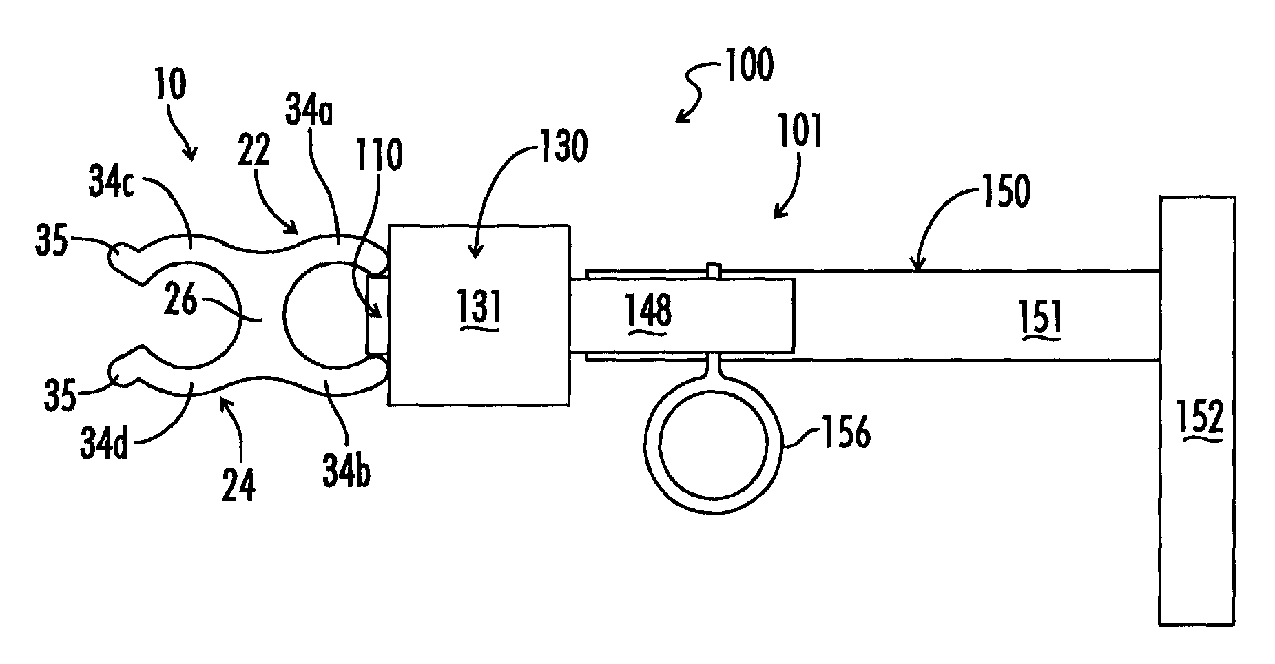
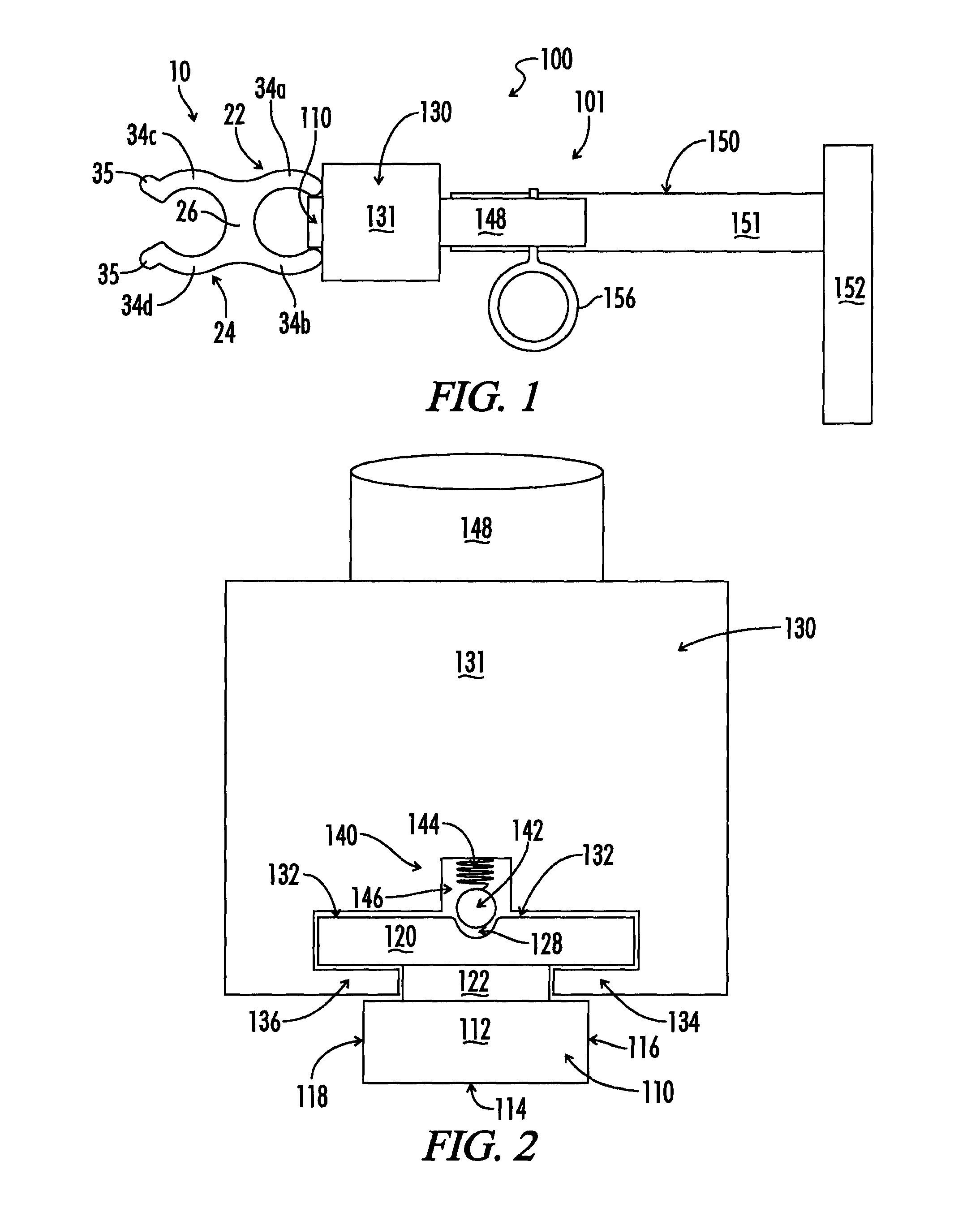
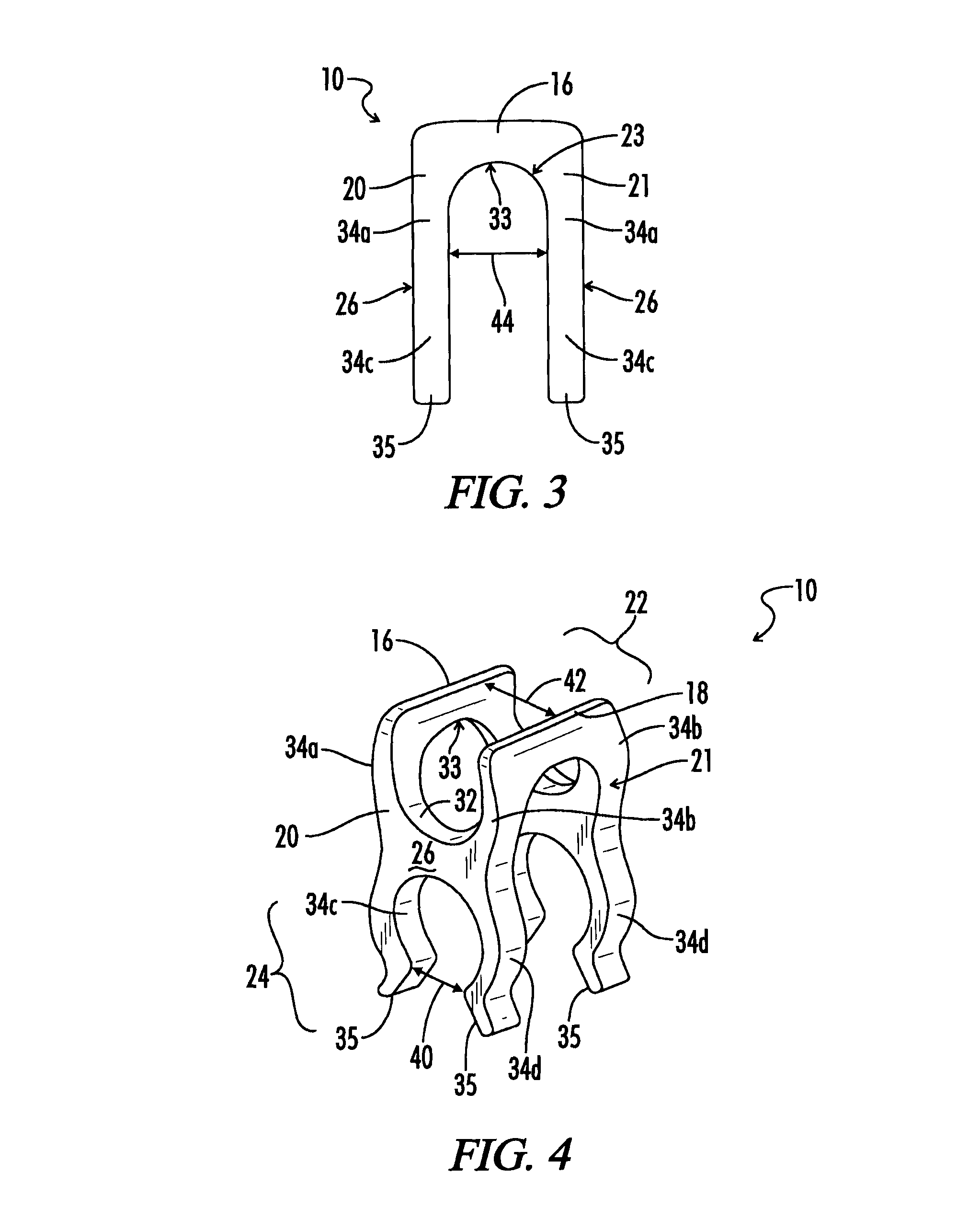
[0023]One preferred embodiment of the bar clip applicator system 100 of the present invention is shown in FIG. 1. The bar clip applicator system 100 includes a novel reinforcement bar clip 10 friction fitted upon the receiver tip 110 of a bar clip applicator 101. The novel reinforcement bar clip 10 includes a plurality of clasp assemblies. The embodiment shown in FIGS. 1, 3 and 4 comprises a pair of opposing first and second clasp assemblies 20, 21. Each first and second clasp assembly 20, 21 is attached to parallel first and second longitudinal supports 16, 18 and extends downward from the longitudinal supports 16, 18. The opposing first and second clasp assemblies 20, 21, together with the first and second longitudinal supports 16, 18, form a U-shaped profile, as is shown in FIG. 3.

[0024]Referring again to FIGS. 1, 3 and 4, the first and second clasp assemblies 20, 21 each comprise an upper clasp 22 for holding a first reinforcement bar and a lower clasp 24 for holding a second re...


PUM

PropertyMeasurementUnit
flexibleaaaaaaaaaa
frictionaaaaaaaaaa
pressureaaaaaaaaaa

Abstract

A reinforcement bar clip applicator includes an applicator body having a handle and a receiver tip. The receiver tip is adapted to receive reinforcement bar clips made of two opposing clasp assemblies. With the second clasp assembly of the bar clip removably affixed to the receiver tip, the assembly forms a bar clip application system adapted to allow the user to remotely attach the first clasp assembly of the bar clip to a reinforcement bar.

Description

[0001]The present invention relates generally to a system and method of attaching and aligning reinforcing bars in a framework for supporting a concrete matrix. More particularly, this invention pertains to an apparatus and method of attaching bar clips to reinforcing bars so as to join the bars in a framework. Even more particularly, this invention pertains to a clip applicator system for applying bar clips for joining pairs of reinforcing bars in a parallel orientation.[0002]It has been long known in the art of reinforced concrete structures to provide fastening means for aligning and attaching reinforcing bars in a framework prior to encasing such bars in a concrete matrix. One well known fastening means used in forming a framework of reinforcing bars is to wrap adjacent bars with wire ties, or other similar binding materials. Another well known fastening means is to attach such reinforcing bars by welding instead of wrapping. Both of these fastening means provide for attaching b...

Claims


Application Information

Patent Timeline
Patent Type & Authority Patents(United States)
IPC IPC(8): B23P11/00
CPCB25B31/00E04C5/163E04C5/167Y10T29/53783Y10T29/5377
Inventor KODI, JON R.
Owner DAYTON SUPERIOR CORP
Why Eureka
Try Eureka