
Microphone

a technology of capacitor microphone and microphone, which is applied in the direction of electrical transducers, electrical transducers, and piezoelectric/electrostrictive transducers, etc., can solve the problem of inferior directional characteristics of the bass sound range to that of the midrange, and achieve favorable directivity, broad frequency characteristic, and enhanced bass sound

Inactive Publication Date: 2011-03-08
SONY CORP
View PDF9 Cites 9 Cited by
  • Summary
  • Abstract
  • Description
  • Claims
  • Application Information

AI Technical Summary

Benefits of technology

This configuration enables the creation of microphones with favorable directivity and broad frequency characteristics in the bass range, eliminating the proximity effect and maintaining cardioid characteristics, thereby improving stereo microphone performance across all frequencies.

Problems solved by technology

Furthermore, a directional characteristic in the bass sound range is inferior to that of a midrange.

Method used


Image

  • Microphone
  • Microphone
  • Microphone

Examples


Embodiment Construction

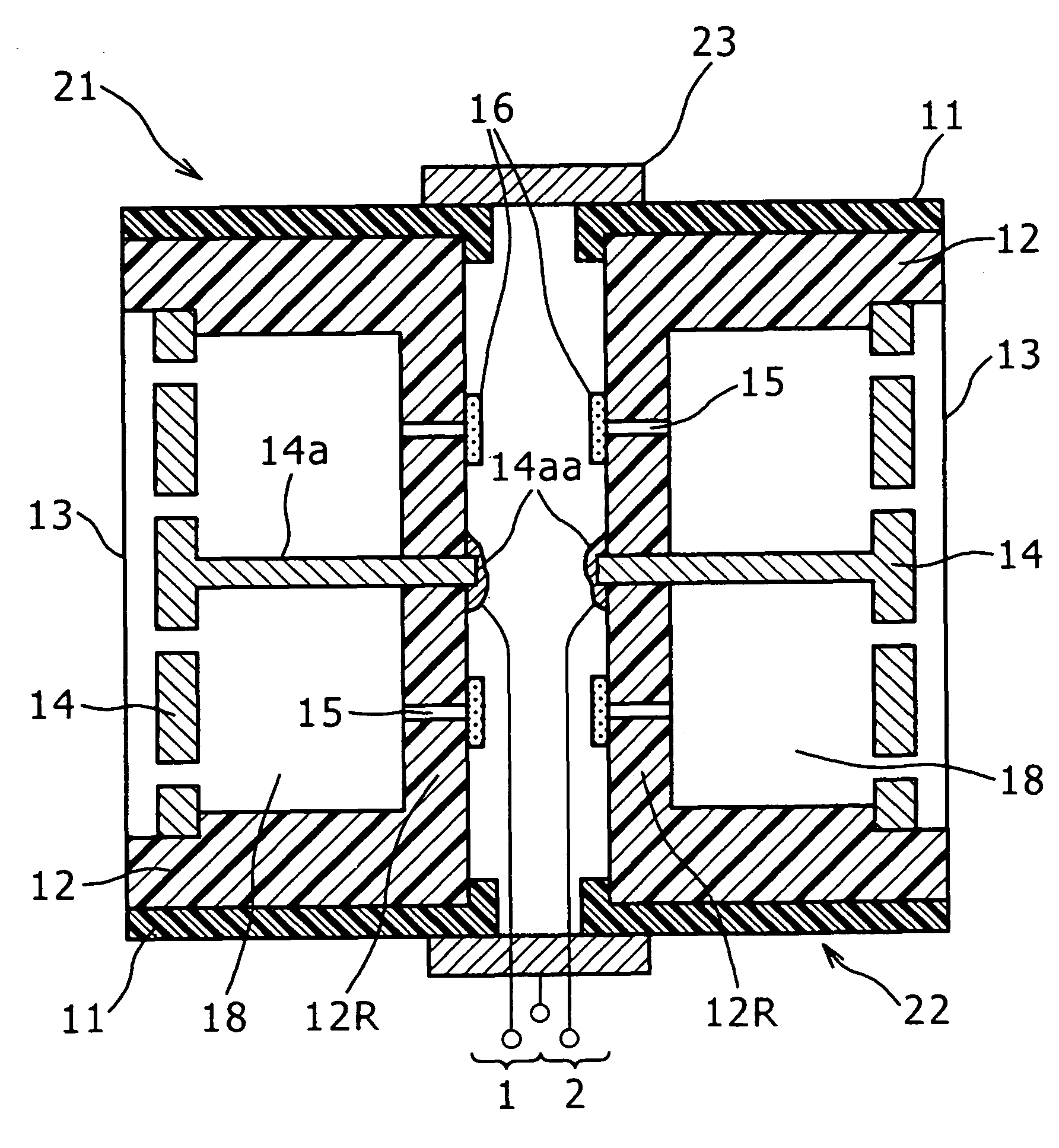
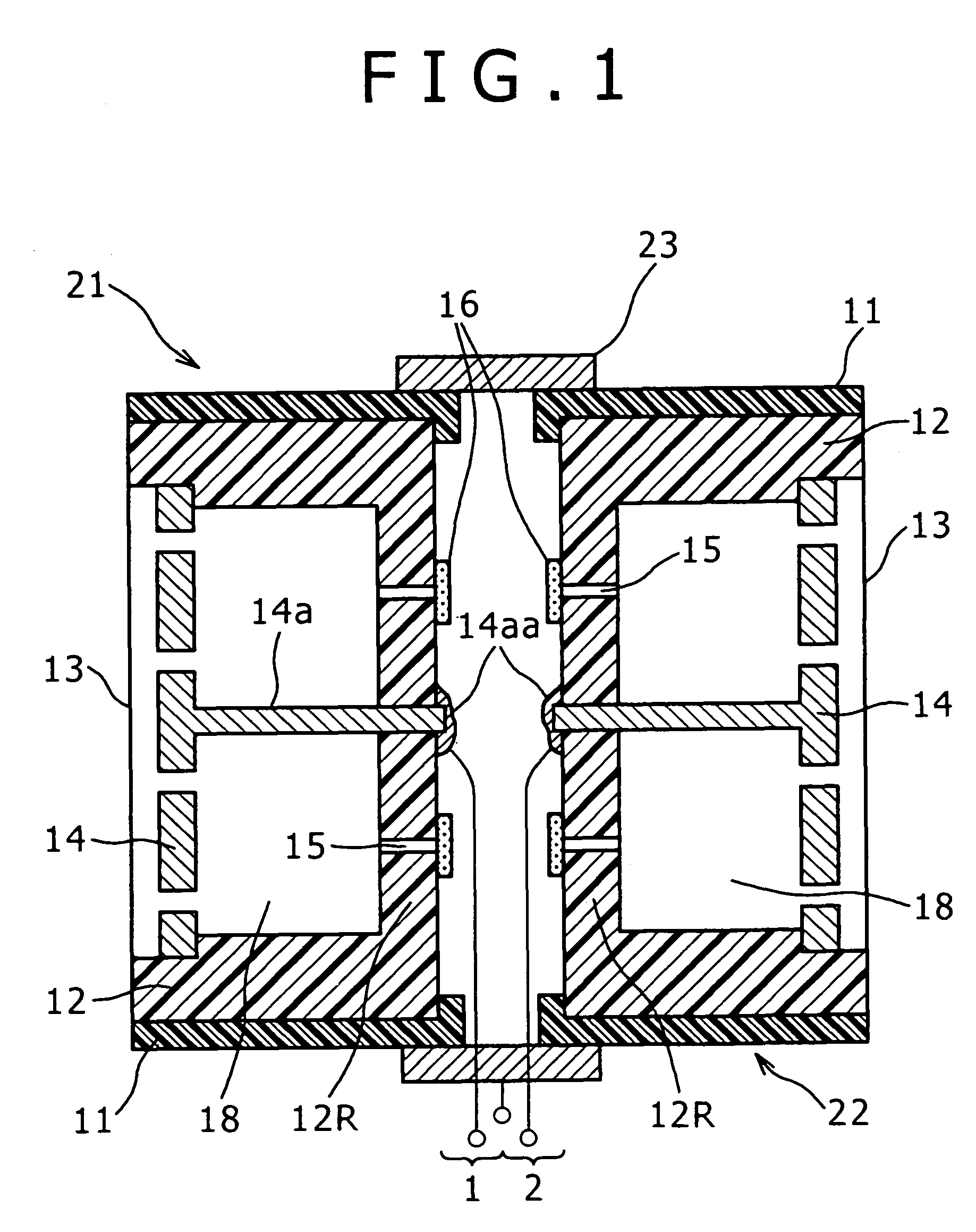
[0037]Hereinafter, an embodiment of the present invention will be described with reference to the accompanying drawings. However, the present invention is not limited to the following embodiment. FIG. 1 shows a bidirectional microphone unit obtained by connecting a pair of the unidirectional microphone units shown in FIG. 8 back to back so as to be opposed to each other. In FIG. 1, the same components are denoted by the same reference numerals as those in FIG. 8.

[0038]Each of the reference numerals 21 and 22 denotes a unidirectional microphone unit configured in the same manner as the microphone unit shown in FIG. 8. The rear plates 12R of the unidirectional microphone units 21 and 22 are arranged to be opposed to each other with a predetermined gap there between. The outer casings 11 of the microphone units 21 and 22 are connected to each other with a metal connection ring 23 having an axial dimension which allows the connection of the two microphone units 21 and 22.

[0039]In the bi...


PUM


Abstract

A microphone having: a first bidirectional microphone unit formed by connecting two unidirectional microphone units, each of which has a vibrating section on a front side thereof, back to back; and a second bidirectional microphone unit formed by connecting two unidirectional microphone units, each of which has a vibrating section on a front side thereof, back to back, and a directional axis of the second bidirectional microphone unit is arranged to be shifted by 90 degrees with respect to a directional axis of the first bidirectional microphone unit.

Description

BACKGROUND OF THE INVENTION[0001]1. Field of the Invention[0002]The present invention relates to a capacitor microphone capable of providing favorable directivity and frequency characteristic.[0003]2. Description of the Related Art[0004]An output voltage of a capacitor microphone unit is proportional to a displacement of a vibrating membrane. If the capacitor microphone unit is configured as a non-directional microphone unit, the capacitor microphone unit has no frequency dependence at a frequency lower than a resonance point of a vibrating system. However, once directivity is provided for the capacitor microphone unit, an electromotive force applied to the vibrating membrane has frequency dependence.[0005]FIG. 8 shows the most standard configuration of a unidirectional microphone unit. FIG. 8 shows an internal structure of the directional microphone unit. In a cylindrical outer casing 11, a case 12 having a rear plate 12R on one end of a cylindrical body in an axial direction is ho...

Claims


Application Information

Patent Timeline
Patent Type & Authority Patents(United States)
IPC IPC(8): H04R25/00H04R3/00H04R9/08
CPCH04R3/005H04R5/027H04R3/00H04R19/04
Inventor KUBOTA, HIROHISA
Owner SONY CORP
Learn More