
Cartridge device for blood analysis

a blood analysis and cartridge technology, applied in the field of cartridge devices for blood analysis, can solve the problems of affecting the flow of blood in tissues of vital importance, affecting the quality of blood, so as to improve the analytical signal, improve the analytical effect, and improve the effect of conductivity

Active Publication Date: 2011-03-08
ROCHE DIAGNOSTICS OPERATIONS INC
View PDF17 Cites 53 Cited by
  • Summary
  • Abstract
  • Description
  • Claims
  • Application Information

AI Technical Summary

Benefits of technology

The present invention provides a cartridge device for analyzing blood that is economical, reproducible, safe, and easy to use. The device includes a cell for receiving blood samples and a stirring device for circulating the blood sample within the cell. The device also includes at least two electrodes for measuring the electrical impedance between the electrodes. The device can measure the change in impedance during the process of aggregation and can discard and repeat the measurements if the variation is outside a predetermined threshold range. The device can be provided ready to use and is well-suited for full automation of the production process. The invention also provides a method for analyzing blood-platelet aggregation using a disposable test cell and a double-determination of the impedance values to control the analysis. The invention allows for the assessment of whole blood aggregation in a routine setting and is not limited to the use of platelet-rich plasma.

Problems solved by technology

When the platelets aggregate, they become sticky and, as a result thereof, they stick to each another and to the damaged tissue.
However the adhesion and aggregation of platelets can also be extremely dangerous when the platelets mistake an aged or inflamed vessel for a vascular injury and thus impair blood flow in tissues of vital importance.
Besides their beneficial effect—to reduce the incidence of platelets closing vitally important vessels—these drugs may also induce bleeding.
However a larger danger is due to the fact that in some of the patients the drugs seem not to work properly.
Current studies have shown that up to 25% of the patients treated do not adequately respond to this treatment.
A disadvantage of this technique is the necessity of producing PRP, whose extraction is a complicated, time-consuming and thus expensive procedure.
Furthermore, the aggregation of platelets is not measured in its natural environment, blood, thus the influence of red and white cells on the platelets is not measured.
Other methods disclosed in documents U.S. Pat. No. 4,604,894 of Kratzer and Born, U.S. Pat. No. 6,010,911 of Baugh et al. and U.S. Pat. No. 5,922,551 of Durbin et al. require relatively complex and expensive cartridges interfering with the use of these techniques for routine testing.
One disadvantage of precious metal electrodes is high costs.
Hence they are too expensive to be disposable.
Therefore, the electrode assembly must be cleaned by hand between tests, exposing the operator to contact with the sample, and thus potentially exposing the operator to diseases transmitted through the fluids contained in the sample.
Since diseases such as hepatitis and AIDS can be transmitted through handling of blood products, there is an understandable reluctance on the part of medical professionals to handle blood, blood products and objects contamined therewith.
A further disadvantage of this structure is due to the fact that the electrodes of the aggregometer have to be handled by the user during the cleaning procedure, potentially disturbing the adjustment of the distance between the electrodes, causing inconsistent results.
Furthermore each electrode requires exact placement of the wires during fabrication, making the final product expensive.
However this device is detrimental due to the fact that the platelets have difficulties in adhering to the exposed conductive surface of the Freilich device. sometimes the aggregated platelets break off the surface, causing a sudden change in impedance.
Hence the measured results by the device are inconsistent and not reproducible.
One drawback of the aforementioned measuring cell device is the use of punched sheet metal for the electrodes 2.
However the surface qualities produced by these methods are relatively poor and vary during the production of large quantities (because of the aging of the punching blades applied during the process).
A further disadvantage is due to the fact that the complete measuring cell device consists of six different pieces, namely the two electrodes 3, the insulator 1, the coating, a cuvette 6, a positional clip 7 and a stir bar 8.
This results in an expensive, complicated production process, which is either labor intensive or requires high investments for an automated assembly line.
Additionally the measuring cell device of Freilich does not overcome the relatively high variation reported for whole blood aggregometry.

Method used


Image

  • Cartridge device for blood analysis
  • Cartridge device for blood analysis
  • Cartridge device for blood analysis

Examples


first embodiment

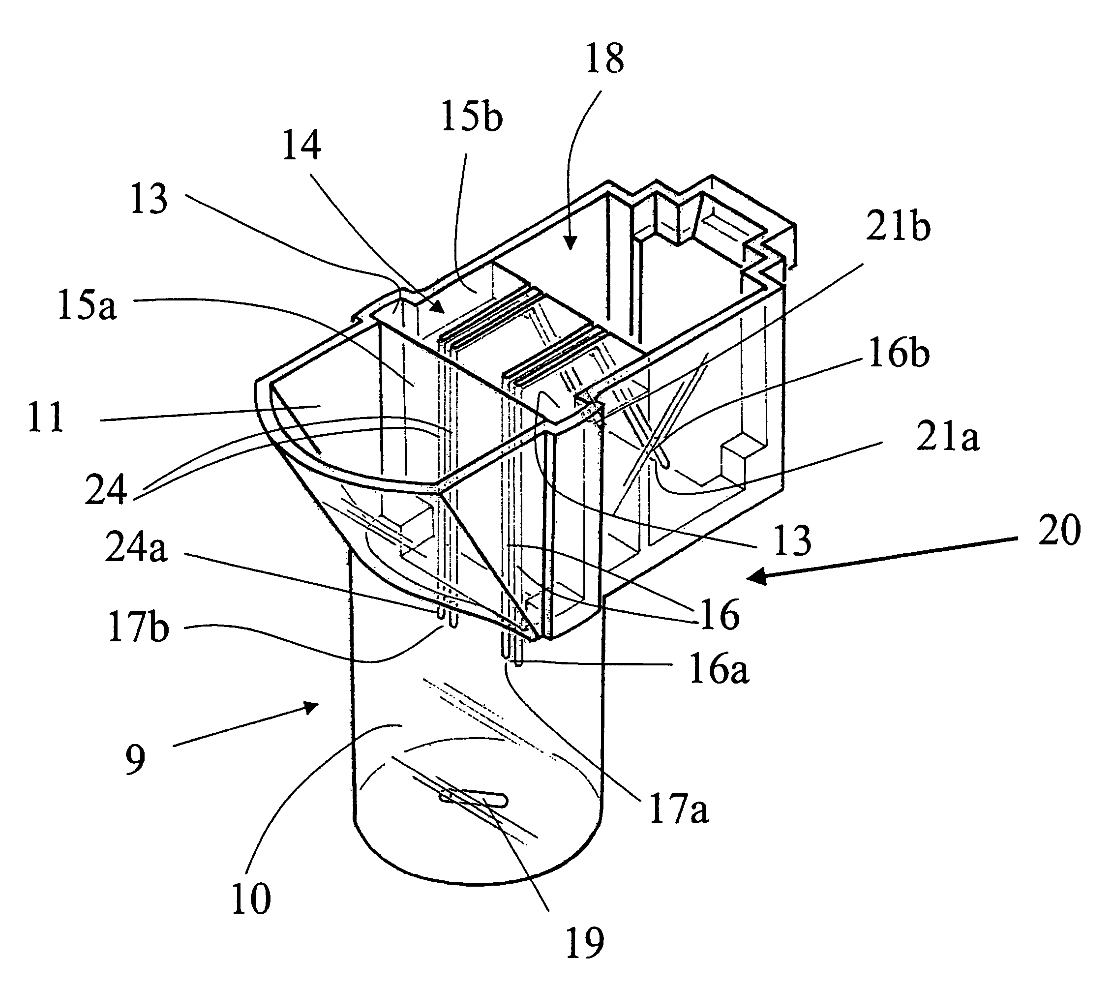
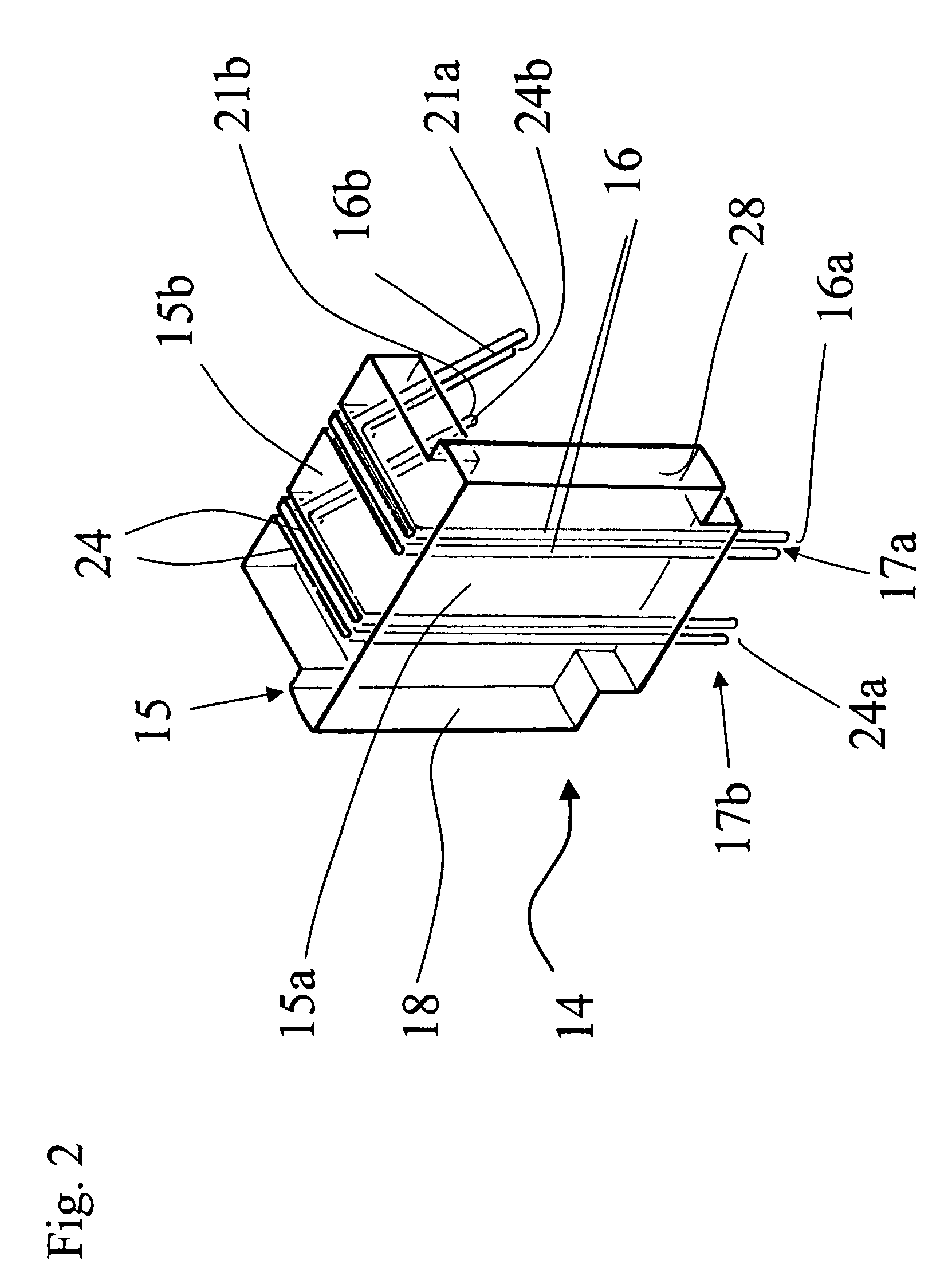
[0055]The other part of the cartridge device 20 is the electrode holder 14, illustrated in FIG. 2 in a perspective view according to the present invention. The electrode holder 14 consists particularly of a plastic body 15, in which two tiny electrode wire pairs 16, 24 are incorporated. Each wire of a wire pair 16, 24 has preferably a diameter of about 0.1-0.5 mm, most preferably 0.3 mm.

[0056]The electrode holder 14 comprises especially a L-formed body 15 with a long part 15a and a short part 15b perpendicular to the long part 15a. At the face side of the long part 15a of the electrode holder 14 each electrode wire of the electrode pairs 16, 24 protrudes and forms a sensor portion 16a, 24a. For example, two sensor portions 16a or 24a form together a sensor unit 17a or 17b. During the analysis the sensor units 17a and 17b are completely immersed into the blood sample. The blood platelets adhere on the sensor portions 16a, 24a of the wire pairs 16, 24 and change the electrical impedan...

second embodiment

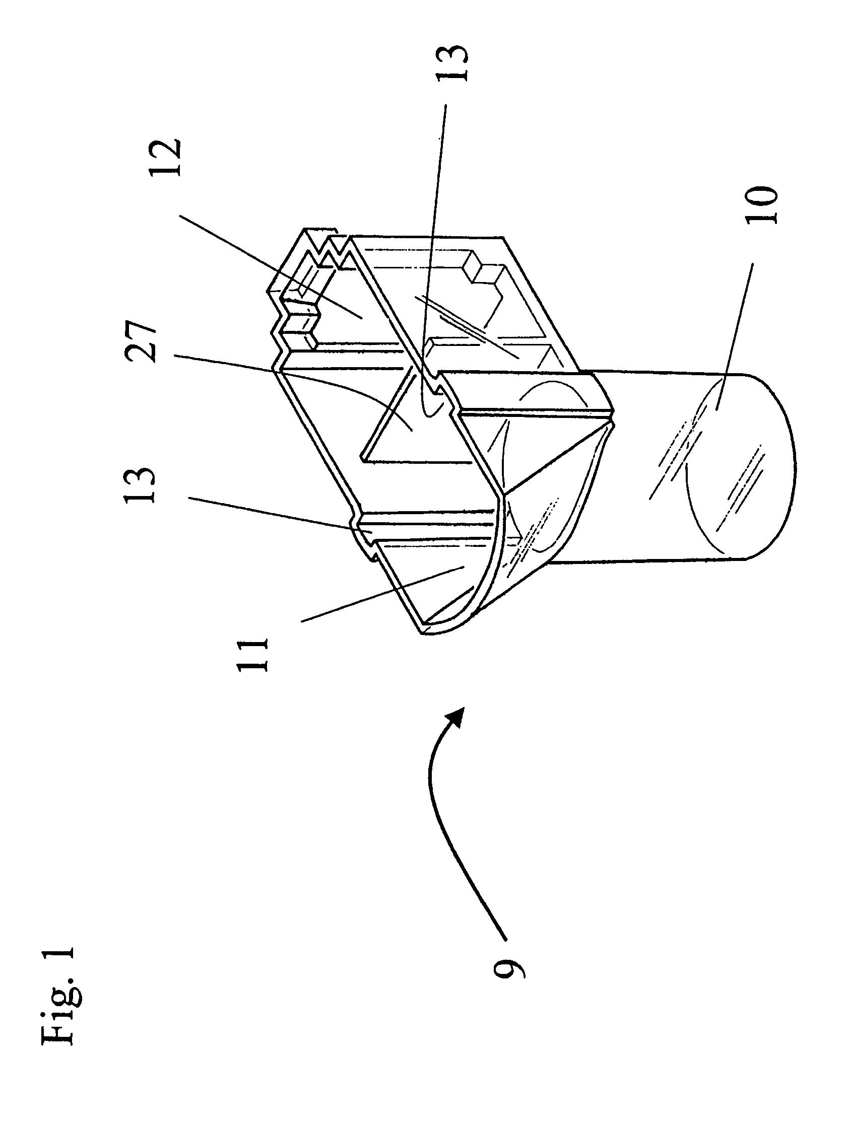
[0077]A second preferred embodiment of the cartridge device 20 is shown in FIG. 8, which is a perspective view. The cell 9 is identical to the previous embodiment and therefore it is referred to the above evaluations.

[0078]However contrary to the first embodiment the electrode holder 14 according to the second embodiment comprises three sensor units 17a, 17b, 17c, which are linearly arranged to each other. Each sensor unit consists of a pair of electrode wires 16, 24 and 25, respectively. Due to the linear arrangement the electrode wire pair 24 is in the middle of the two remaining electrode wire pairs 16 and 25 and is exposed to a significantly lower blood flow when compared to the outer electrode wire pairs 16 and 25. Hence according to the second embodiment it is possible to compare platelet adhesion and aggregation under varying flow conditions. It is obvious to a person skilled in the art that by variations of the number and geometric arrangement of the test units the flow con...

fourth embodiment

[0082]FIG. 10 illustrates a top plan sectional view of a cartridge device 20 according to the present invention. The cell 9 is identical to the aforementioned embodiments and therefore it is referred to the above evaluations.

[0083]However the electrode holder 14 is formed to allow a circular arrangement (FIG. 8) of several sensor units. According to the present arrangement shown in FIG. 10 three sensor units 17a, 17b and 17c are arranged at the same radial location in the blood sample, i.e. in the receiving portion 10, and exposed to the identical or nearly identical blood flow, which allows to directly compare the signals.

[0084]According to the fourth embodiment the analyser independently records the changes in conductivity between the wire pairs of the three sensor units 17a, 17b and 17c. Thus three independent results are obtained. For example the mean or median value is reported to the user, resulting in an enhanced precision of the analysis when compared to the prior art and to...


PUM

PropertyMeasurementUnit
thicknessaaaaaaaaaa
diameteraaaaaaaaaa
diameteraaaaaaaaaa

Abstract

A cartridge device having a receiving portion for receiving a blood sample and a jack portion for receiving a plug; a stirring device for circulating the blood sample within the receiving portion; and an electrode holder having at least one incorporated electrode wire pair; wherein the electrode holder is attachable to the cell such that one end of the at least one electrode wire pair forms a sensor unit for measuring the electrical impedance between the two electrode wires of the at least one electrode wire pair within the blood sample and that the opposite end of the at least one electrode wire pair forms a plug portion being connectable directly to the plug for an electrical connection of the sensor unit to an analyser.

Description

TECHNICAL FIELD[0001]The present invention relates to a cartridge device for blood analysis and a method for testing platelet functions.BACKGROUND ART[0002]Though the present invention can be used in many fields of measuring fluids it will be described in regard to measuring the platelet function of blood in the following.[0003]Blood consists of cells suspended in so called plasma, a protein rich fluid. The major groups of cells in the blood are red cells, white cells and platelets. The platelets are responsible for plugging gaps or holes in the blood vessel wall. This is achieved by a mechanism called aggregation-adhesion reaction. When the platelets aggregate, they become sticky and, as a result thereof, they stick to each another and to the damaged tissue. Usually this happens when the platelets come into contact with certain materials and chemicals, especially those related to damaged cells.[0004]Platelet adhesion to injured blood vessels is an essential property in order to clo...

Claims


Application Information

Patent Timeline
Patent Type & Authority Patents(United States)
IPC IPC(8): G01N33/48B01L3/00G01N27/02G01N33/86G01N27/07G01N33/49
CPCG01N27/07G01N33/86G01N33/4905B01L3/502B01L2200/028B01L2300/0645B01L2300/046
Inventor CALATZIS, ANDREASKRUGER, BENWITTWER, MARC
Owner ROCHE DIAGNOSTICS OPERATIONS INC
Learn More