
Label printer

a label printer and label technology, applied in the field of label printers, can solve the problems of limited availability of label printers, and achieve the effect of ensuring the accuracy of the laminating position between the first and second labels, and avoiding the occurrence of tripping

Active Publication Date: 2011-03-08
LINTEC CORP
View PDF10 Cites 8 Cited by
  • Summary
  • Abstract
  • Description
  • Claims
  • Application Information

AI Technical Summary

Benefits of technology

[0018]According to the label printer of the present invention, since the second label is formed smaller than the first label in plane area and, after laminating the second label on the first label, the labels are stuck with the second label sandwiched between the first label and the object, the entire peripheral area of the first label can be stuck to the object. Accordingly, partial floating or the like in the outer periphery of the stuck label can be prevented effectively; and thus, the information printed on the second label can be completely concealed.
[0019]Also, since the second label suction plate is arranged movably forward and backward along the feed out direction of the label, positional adjustment is possible along the feed-out direction when sticking the second label to the adhesive layer side of the first label.
[0020]Further, by forming the tear-off line and the notch portion within a surface of the first label, the second label can be torn off easily along with a part of the first label; and the roll-up portion can be used on the tearing off.
[0021]Furthermore, since the label suction faces of the first holding means and the second holding means substantially correspond to the plane area of the first and second labels respectively, the suction position between the labels can be adjusted with great ease; and thus the accuracy of the laminating position between the first and second labels can be satisfactorily ensured.

Problems solved by technology

However, when a delivery slip of this type is employed, the available label printer is limited.

Method used


Image

  • Label printer
  • Label printer
  • Label printer

Examples


Embodiment Construction

[0046]Now, referring to the drawings, preferred embodiments of the present invention will be described.

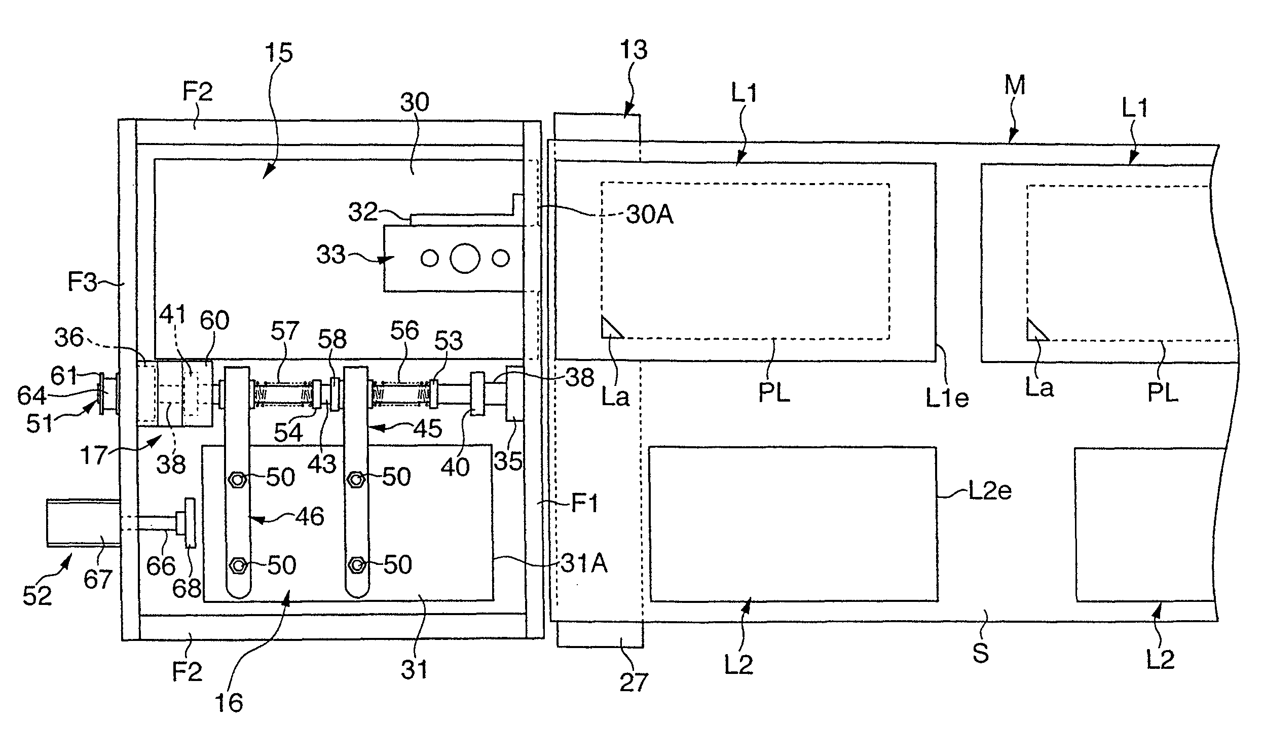
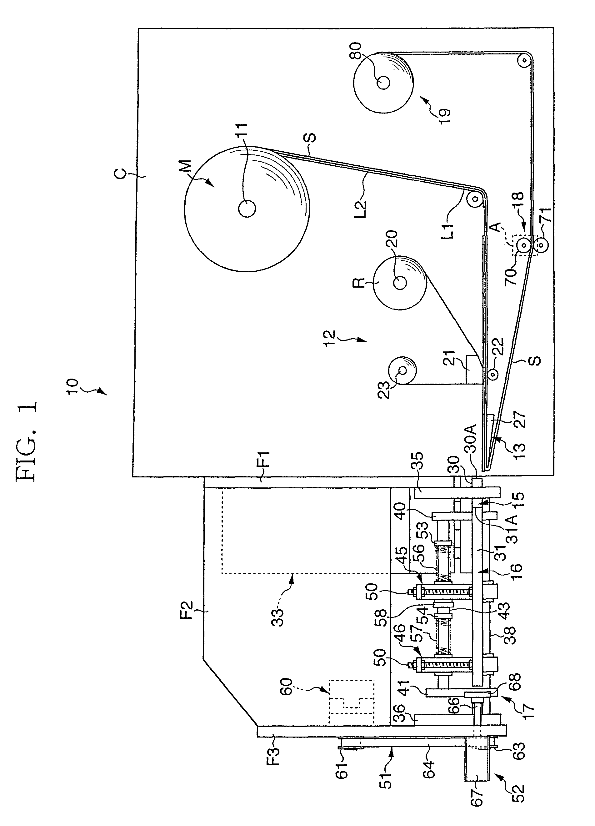
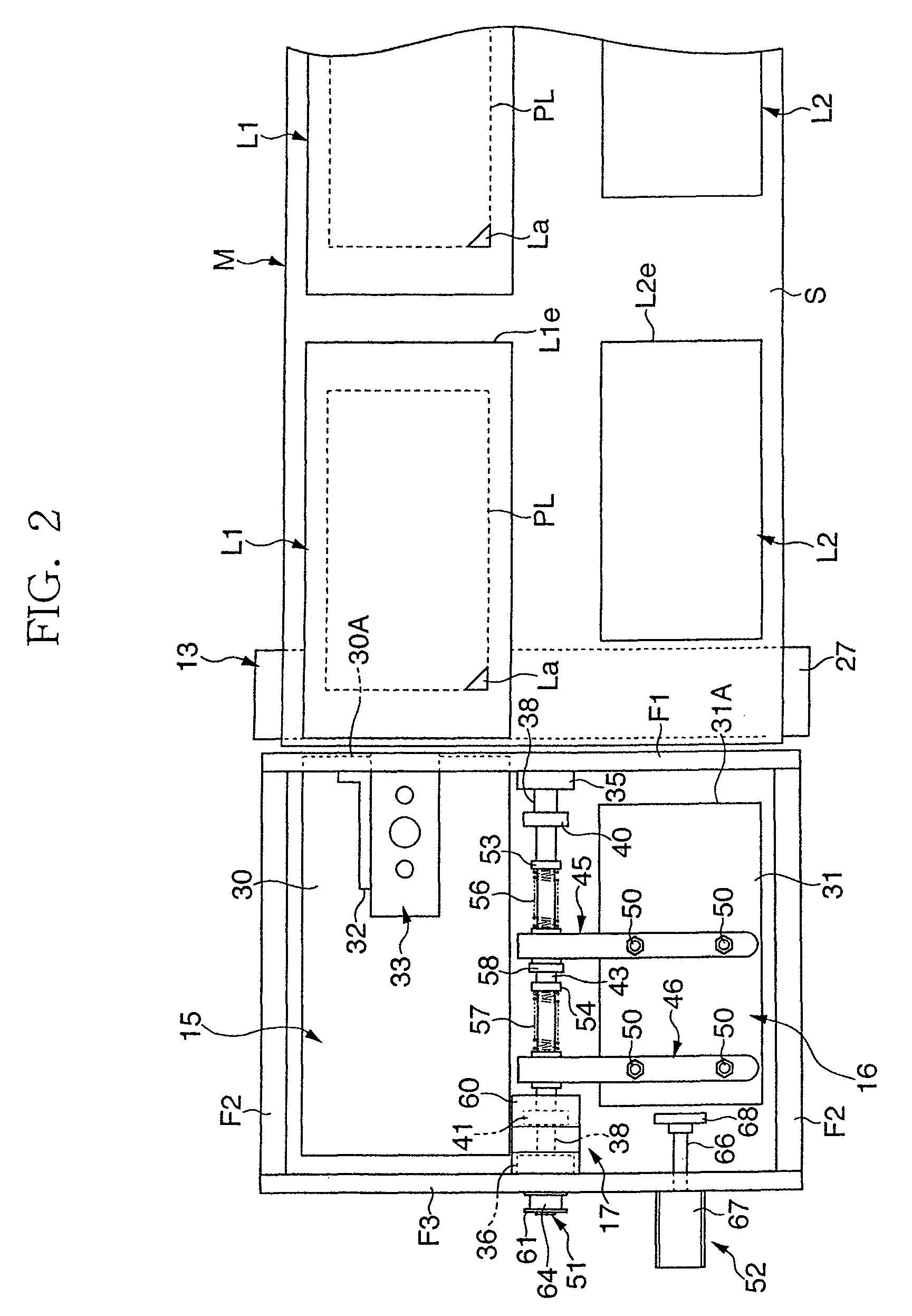
[0047]FIG. 1 shows a schematic front view of a label printer according to an embodiment of the present invention, and FIG. 2 shows a schematic plan view thereof. Referring to these figures, a label printer 10 includes a printer case C; a support roll 11 provided within the printer case C and serving as a feed-out means that supports a raw strip sheet M, which is temporarily stuck with first and second labels L1, L2 on one surface of a strip of release liner S, so as to be capable of feeding out the raw strip sheet M therefrom; a printing means 12 that performs printing on the first and second labels L1, L2 on the way of feeding out the raw strip sheet M; a peeling means 13 that peels off the first and second labels L1, L2 from the release liner S; first and second label holding means 15, 16 that hold the first and second labels L1, L2, respectively, which are peeled off by the peel...


PUM

PropertyMeasurementUnit
rotation angleaaaaaaaaaa
plane areaaaaaaaaaaa
adhesiveaaaaaaaaaa

Abstract

There is provided a printing device 12 that performs printing on each of first and second labels L1, L2 on the way of feeding out a raw strip sheet M, which is temporarily stuck with a first label L1 and a second label L2 having a smaller plane area than that of the first label on a release liner S, a peel plate 27 that peels off the first and second labels L1, L2 from the release liner S, first and second label suction plates 30, 31 that hold the respective peeled labels L1, L2, and a laminating device 17 that laminates the first and second labels L1, L2 with the adhesive layer of the second label L2 facing the adhesive layer of the first label L1. The adhesive layer of the first label L1 laminated with the second label L2 is exposed in a closed loop manner in an outer peripheral area all around the second label L2.

Description

RELATED APPLICATIONS[0001]The present application is based on, and claims priority from, International Application No. PCT / JP06 / 300466, filed Jan. 17, 2006, and Japan Application Number 2005-017671, filed Jan. 26, 2005, the disclosures of which are hereby incorporated by reference herein in their entirety.TECHNICAL FIELD[0002]The present invention relates to a label printer, in particular to a label printer suitable for sticking a first label and a second label to an object so as to be stuck in a state that the second label is positioned at an adhesive layer side of the first label and sandwiched between the object and the first label.BACKGROUND ART[0003]Recently, accompanying a global-wide expansion of the Internet, TV shopping and the like, in addition to a conventional over-the-counter sale, mail-order sale has come into wide use. In the mail-order sale, a deliverer delivers an article in place of a seller, and as common payment methods for the cost arisen from that, payment by b...

Claims


Application Information

Patent Timeline
Patent Type & Authority Patents(United States)
IPC IPC(8): B65C9/26
CPCB31D1/021B31D1/027B65C9/00B65C9/1884B65C9/46Y10T156/1744Y10T156/1702Y10T156/1707Y10T156/16Y10T156/171B65C2009/0053B32B7/12B65C9/0006B65C9/18B65C9/36B65C2009/0009
Inventor DANGAMI, AKIRAKOBAYASHI, KENJI
Owner LINTEC CORP
Learn More