Eureka AIR delivers breakthrough ideas for toughest innovation challenges, trusted by R&D personnel around the world.

Signal encoding device and signal encoding method, signal decoding device and signal decoding method, program, and recording medium

a signal encoding and signal encoding technology, applied in the field of signal encoding devices and signal encoding methods, and program devices, can solve the problem of not being able to obtain good quality of audio signals, and achieve the effect of improving encoding efficiency and reducing the amount of high-frequency gain information

Inactive Publication Date: 2011-03-01
SONY CORP
View PDF11 Cites 21 Cited by
  • Summary
  • Abstract
  • Description
  • Claims
  • Application Information

AI Technical Summary

Benefits of technology

The patent text describes a technology for improving the quality of high-frequency signals by expanding the bandwidth of the signal without changing the format. The technology uses a method called LPC (Linear Predictive Coding) to double the reproduction band of a PCM signal. The text also describes a signal decoding device and method for effectively transmitting and decoding high-frequency signals. The invention provides a solution for effectively transmitting and decoding high-frequency signals in a way that improves quality and reduces distortion.

Problems solved by technology

However, since the auditory distortion sings in the ears, a good quality cannot be obtained with respect to an audio signal.

Method used


Image

  • Signal encoding device and signal encoding method, signal decoding device and signal decoding method, program, and recording medium
  • Signal encoding device and signal encoding method, signal decoding device and signal decoding method, program, and recording medium
  • Signal encoding device and signal encoding method, signal decoding device and signal decoding method, program, and recording medium

Examples


Embodiment Construction

[0038]Hereinafter, detailed embodiments of the invention will be described with reference to the accompanying drawings.

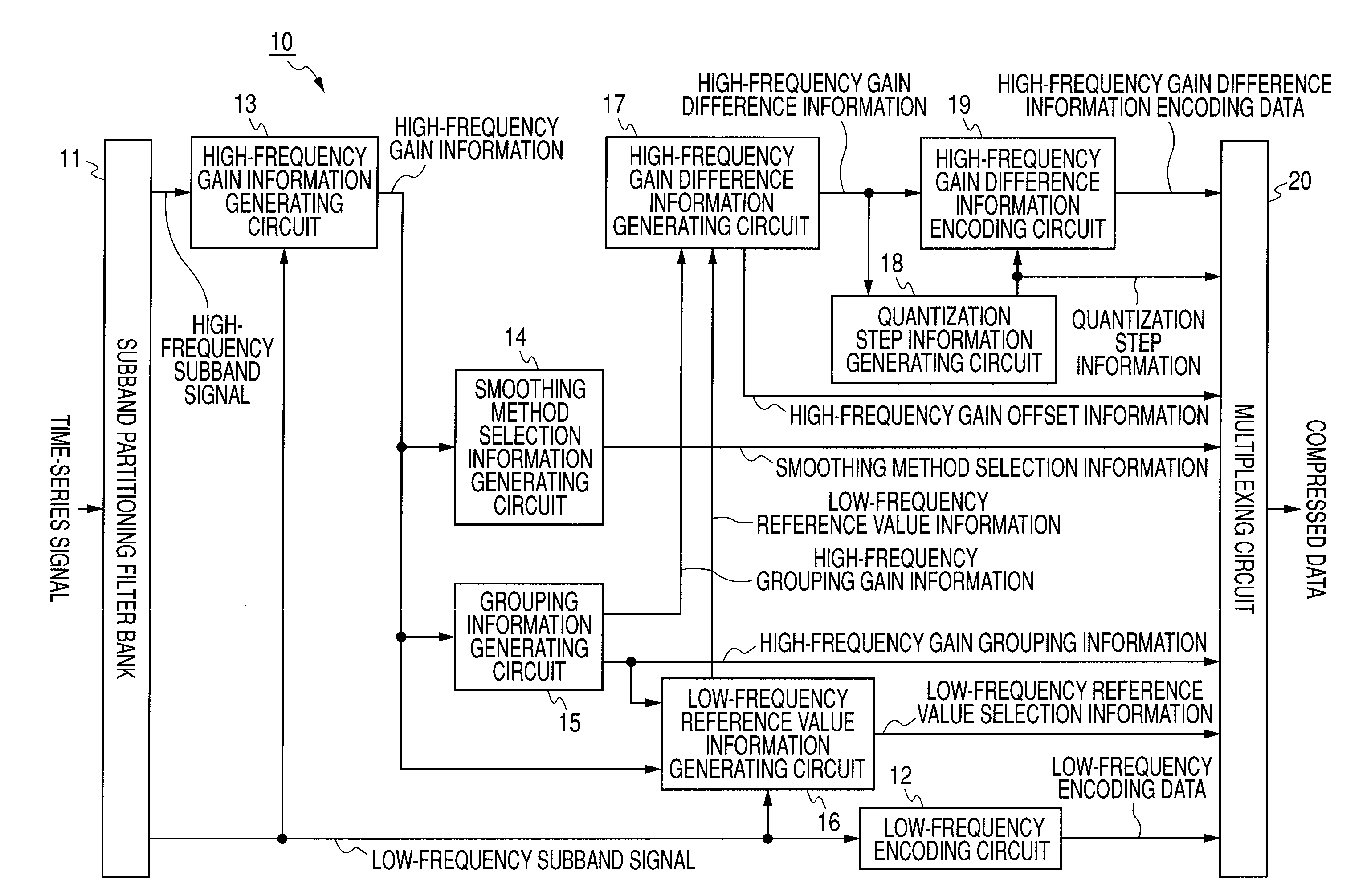
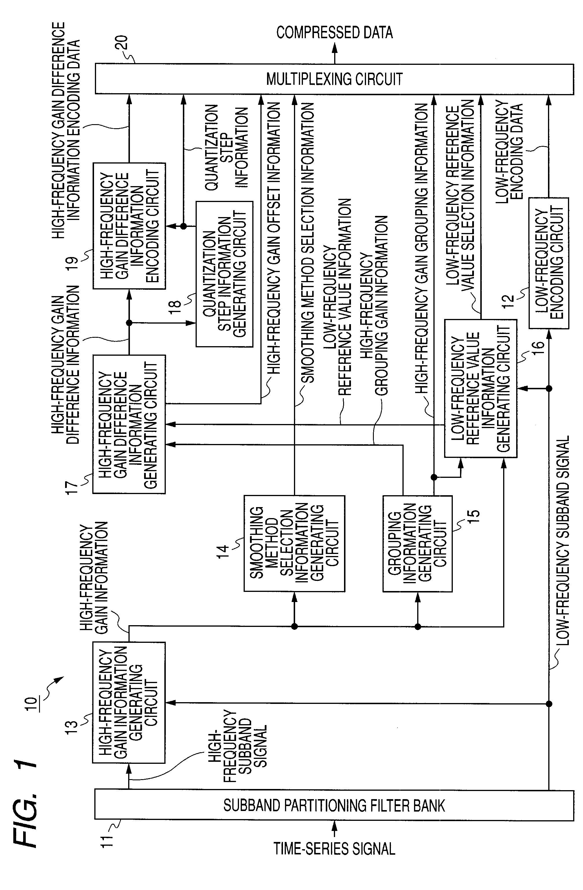
[0039]First, FIG. 1 is a schematic view of a signal encoding device according to an embodiment of the invention. As shown in FIG. 1, a signal encoding device 10 in this embodiment of the invention includes a subband partitioning filter bank 11, a low-frequency encoding circuit 12, a high-frequency gain information generating circuit 13, a smoothing method selection information generating circuit 14, a grouping information generating circuit 15, a low-frequency reference value information generating circuit 16, a high-frequency gain difference information generating circuit 17, a quantization step information generating circuit 18, a high-frequency gain difference information encoding circuit 19, and a multiplexing circuit 20.

[0040]The subband partitioning filter bank 11 partitions an input time-series signal into plural subbands, and provides a low-frequency subband...


PUM


Abstract

A signal encoding device for encoding an input time-series signal includes: partitioning means; low-frequency encoding means; high-frequency gain information generating means; low-frequency reference value information generating means; high-frequency gain difference information generating means; high-frequency gain difference information encoding means; and multiplexing means.

Description

CROSS REFERENCES TO RELATED APPLICATIONS[0001]The present invention contains subject matter related to Japanese Patent Application JP 2005-372518 filed in the Japanese Patent Office on Dec. 26, 2005, the entire contents of which being incorporated herein by reference.BACKGROUND OF THE INVENTION[0002]1. Field of the Invention[0003]The present invention relates to a signal encoding device and a signal encoding method, a signal decoding device and a signal decoding method, a program, and a recording medium suitably applicable to expand a time-series signal limited to a frequency band at an encoding side to wider frequency band at a decoding side.[0004]2. Description of the Related Art[0005]In recent years, it has become possible to compress a tone quality corresponding to a CD (Compact Disc) in data amount of approximately 1 / 10 of the original CD by using a human's auditory structure in high-efficiency encoding of an audio signal. Products manufactured by using the technology are prese...

Claims


Application Information

Patent Timeline
Patent Type & Authority Patents(United States)
IPC IPC(8): G10L21/00G10L19/02G10L21/0388
CPCH04B1/667G10L19/02H03M7/30G11B20/10
Inventor HONMA, HIROYUKICHINEN, TORU
Owner SONY CORP
Why Eureka
Eureka Blog
Learn More