
Receiving device for spread spectrum radar apparatus

a spread spectrum radar and receiver technology, applied in the field of receiving devices, can solve the problems of inability to obtain precise radar spectrum, unstable current values of in-phase balanced signal and quadrature balanced signal, and inability to achieve precise radar spectrum

Inactive Publication Date: 2011-03-01
PANASONIC CORP
View PDF22 Cites 4 Cited by
  • Summary
  • Abstract
  • Description
  • Claims
  • Application Information

AI Technical Summary

Benefits of technology

"The present invention provides a receiving device for a spread spectrum radar apparatus that stabilizes signal intensity by keeping constant a sum of squares of an in-phase signal and a quadrature signal without depending on the phase of a reception signal to obtain a precise radar spectrum. The receiving device includes a signal receiving unit, a despreading unit, and a quadrature demodulating unit. The despreading unit generates two despread signals by using a pseudo-noise code, and the quadrature demodulating unit generates the in-phase and quadrature signals by demodulating the despread signals. The current values of the in-phase and quadrature signals can be kept constant by keeping the current values of the lines through which the signals pass. This ensures a stable radar spectrum and prevents distortion."

Problems solved by technology

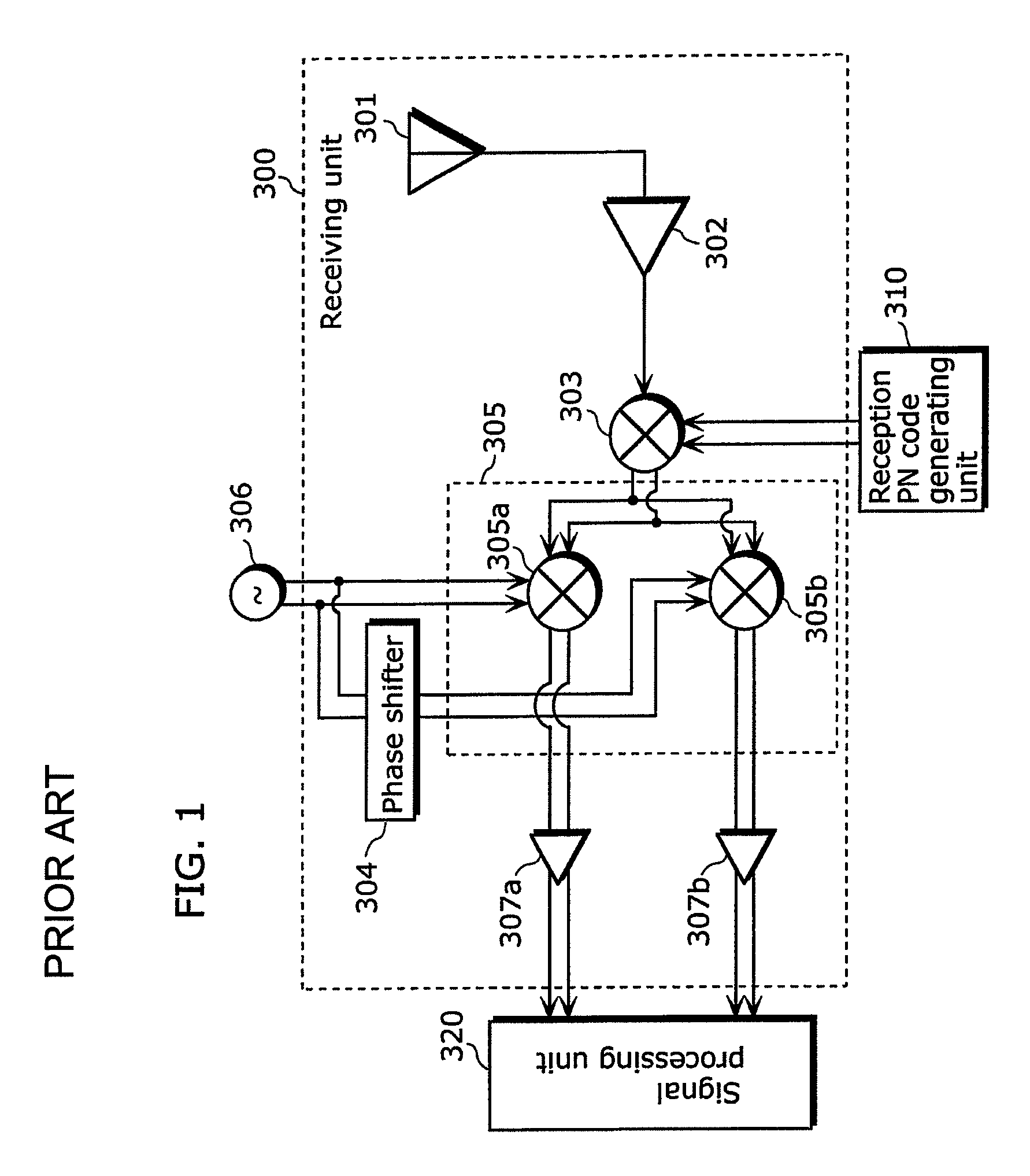
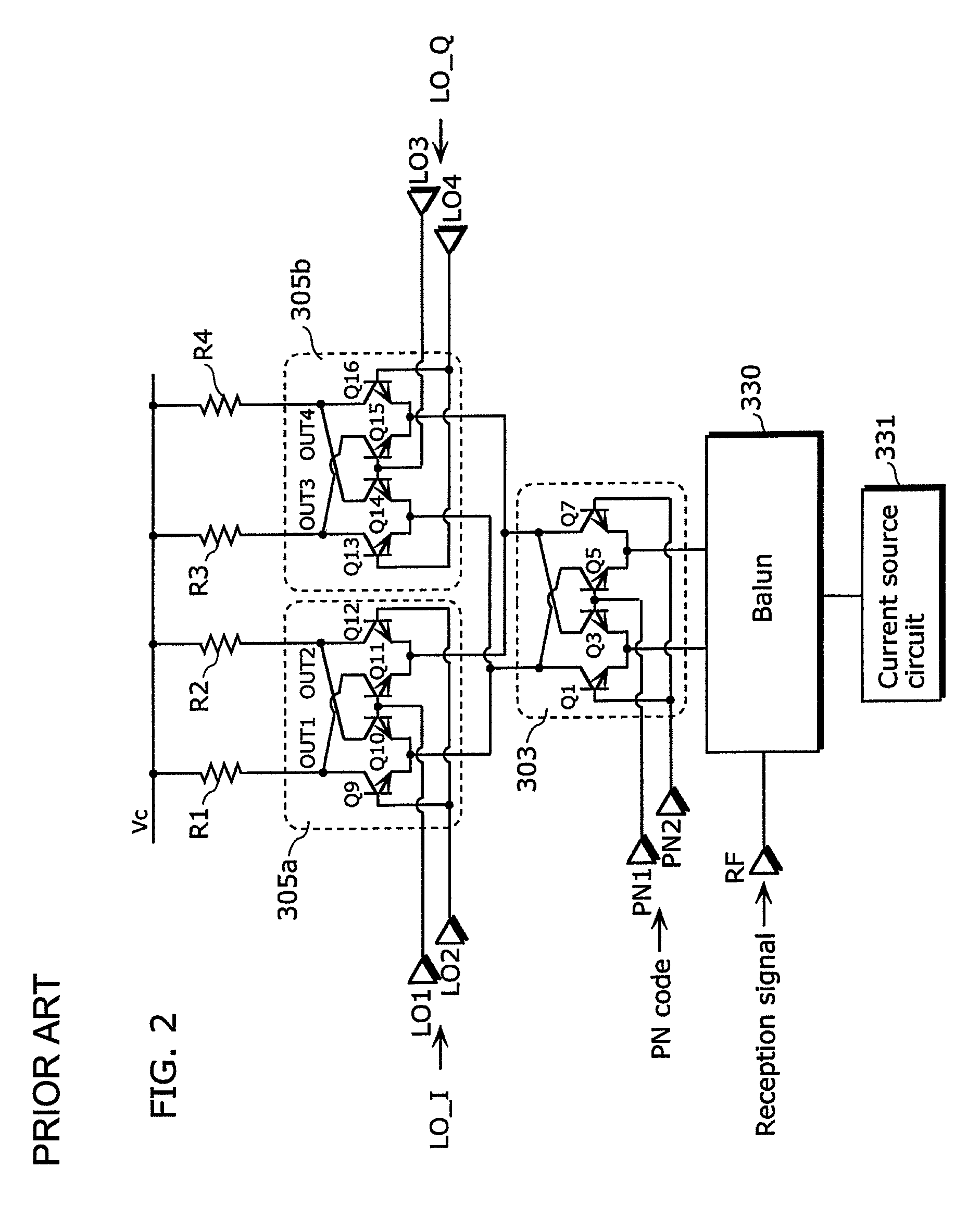
However, such a conventional receiving device has a problem that current values of an in-phase balanced signal and a quadrature balanced signal are not stable and that a reception signal reflected from an object at a certain distance is not stable at its peak.
In other words, when a voltage level of a signal received by a base of each transistor varies due to the influence such as noise, intensity of an output signal also varies and thus a precise radar spectrum cannot be obtained.

Method used


Image

  • Receiving device for spread spectrum radar apparatus
  • Receiving device for spread spectrum radar apparatus
  • Receiving device for spread spectrum radar apparatus

Examples


first embodiment

[0051]A receiving device for a spread spectrum radar apparatus of a first embodiment includes a despreading unit and a quadrature demodulating unit each of which is configured of a switching circuit that is a double balanced I / O circuit. The receiving device further includes a current power source circuit that is shared between the despreading unit and the quadrature demodulating unit. The despreading unit includes 4 transistor pairs each including 2 transistors. The receiving device has a circuit configuration in which 2 transistors included in a transistor pair are connected to each other through the respective bases and emitters. Current values of currents provided from the transistors are set to the same value. Furthermore, the receiving device is, for example, mounted in a moving object, such as a vehicle.

[0052]FIG. 4 schematically illustrates a configuration of a receiving device 100 for a spread spectrum radar apparatus of the first embodiment. The receiving device 100 receiv...

second embodiment

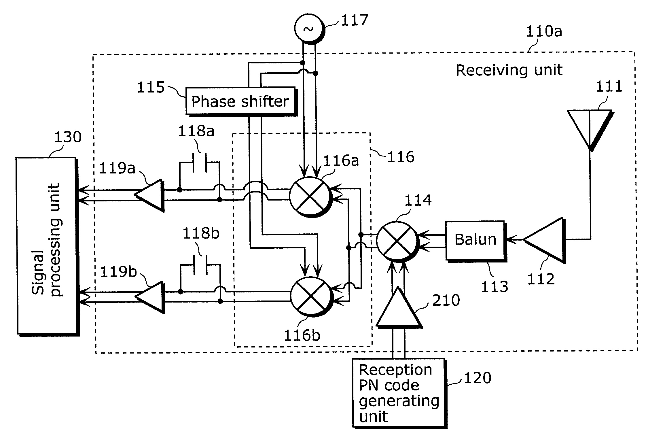
[0084]A receiving device for a spread spectrum radar apparatus of a second embodiment amplifies intensity of a signal of a PN code received by a despreading unit, by inserting a differential amplifier between a reception PN code generating unit and the despreading unit.

[0085]FIG. 9 illustrates a configuration of a receiving device 110a of the second embodiment. The receiving device 110a here differs from the receiving device 110 in FIG. 5 in adding a differential amplifier 210. The following mainly describes the difference by omitting the description of the same characteristics and functions as those of the receiving device 110 in FIG. 5. Here, constituent elements in FIG. 9 identical to those of FIG. 5 are numbered in the same manner as in FIG. 5.

[0086]The receiving unit 110a in FIG. 9 adds, to the constituent elements in FIG. 5, the differential amplifier 210 between the reception PN code generating unit 120 and the despreading unit 114.

[0087]FIG. 10 illustrates a circuit configur...


PUM


Abstract

Provided is a receiving device that is used for a spread spectrum radar apparatus, receives a spectrum-spread signal, and obtains a precise radar spectrum, and includes: a despreading unit that (i) generates first and second despread signals that are generated by despreading a reception signal using a pseudo-noise code, the second despread signal passing through a transmission line carrying a current having a current value identical to a current value of a current carried by a transmission line through which the first despread signal passes, and (ii) includes a first transistor pair including first and second transistors having an identical characteristic, the first transistor outputting the first despread signal, and the second transistor outputting the second despread signal; and a quadrature demodulating unit that generates an in-phase signal and a quadrature signal by quadrature-demodulating the first despread signal and the second despread signal, respectively.

Description

BACKGROUND OF THE INVENTION[0001](1) Field of the Invention[0002]The present invention relates to a receiving device to be used for a spread spectrum radar apparatus using a spread spectrum scheme, and particularly to a receiving device that can obtain a radar spectrum that is precise and has stable intensity without depending on a phase of a reception signal.[0003](2) Description of the Related Arts[0004]In recent years, vehicles have been equipped with radar apparatuses for use in detecting objects, such as vehicles ahead and obstacles behind the vehicles. There are high expectations for such radar apparatuses in terms of improvements in safety, such as avoiding collision, and in convenience of drivers as represented by support for reverse driving operations. Thus, technical developments in radar apparatus to be mounted in vehicles (hereinafter referred to as in-vehicle radar apparatuses) have been active. One of the important tasks of in-vehicle radar apparatuses is to suppress t...

Claims


Application Information

Patent Timeline
Patent Type & Authority Patents(United States)
IPC IPC(8): G01S7/285G01S13/00H03D7/00H03D7/14H04B1/707H04B1/7095H04J13/00
CPCH03D7/165H04B2201/70715
Inventor UJITA, SHINJIFUKUDA, TAKESHI
Owner PANASONIC CORP
Learn More