Photoelectric encoder with a transparent protective material having a thickness equal to or greater than a depth of focus of an image forming optical system disposed on the surface of a scale
a technology of transparent protective material and photoelectric encoder, which is applied in the direction of optical conversion of sensor output, instruments, measurement devices, etc., can solve problems such as the decrease of signal strength, and achieve the effects of small image formation effect, improved reliability of scale dirt, and stabilized signal strength
- Summary
- Abstract
- Description
- Claims
- Application Information
AI Technical Summary
Benefits of technology
Problems solved by technology
Method used
Image
Examples
first embodiment
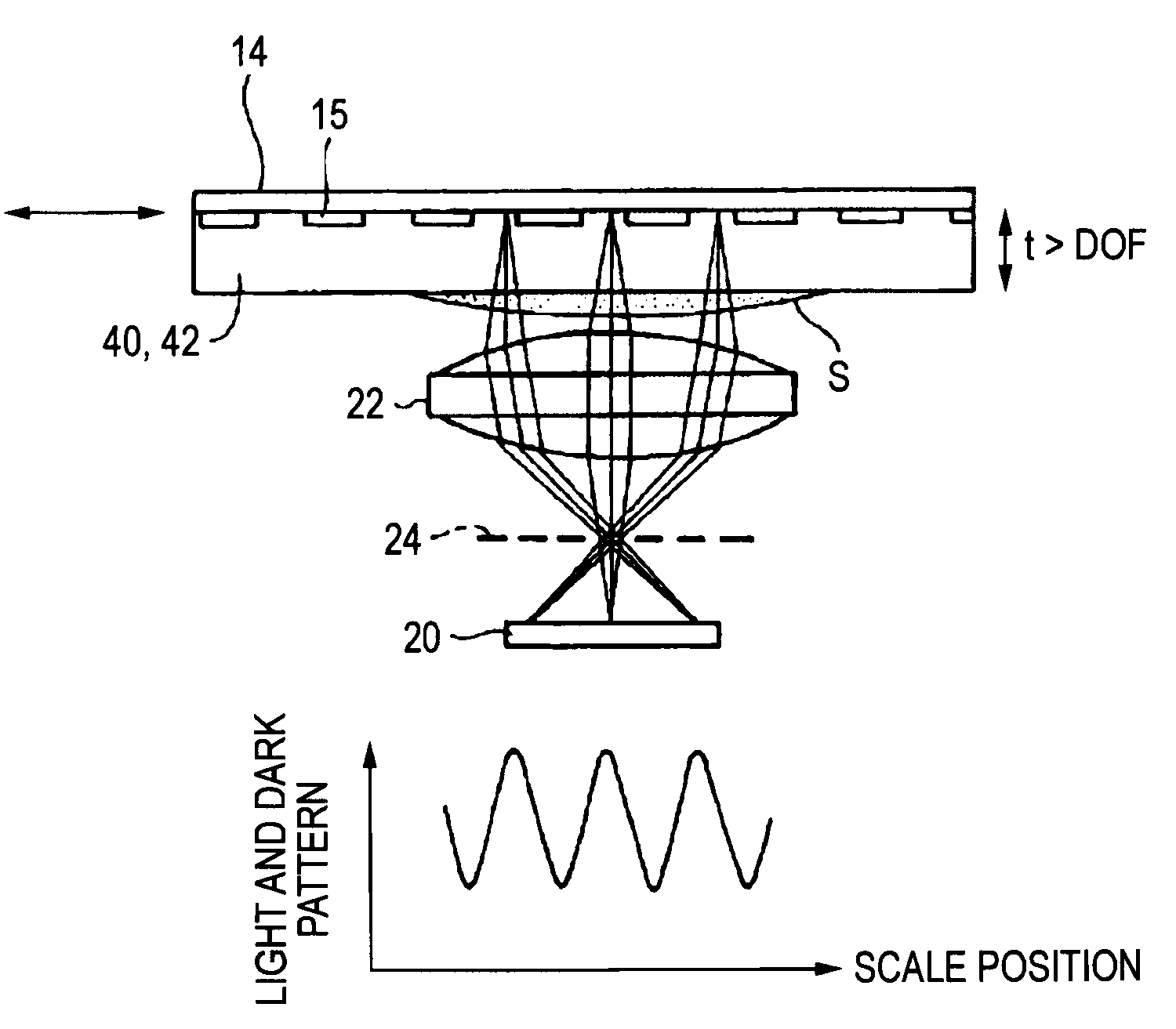
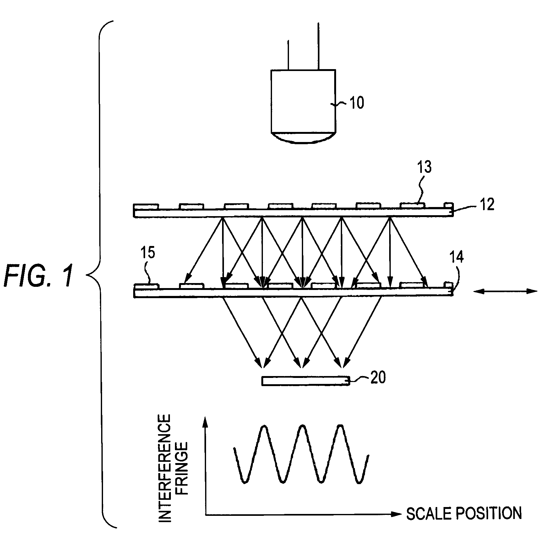
[0033]FIG. 8 shows the invention applied to a transmission encoder like that in FIG. 1 having an image forming optical system made of a lens 22. As shown in FIG. 8, a transparent protective material 40 or 42 is disposed on a grating 15 side surface of a scale 14, whereby dirt S is deposited on the transparent protective material 40 or 42 rather than on the grating 15 face of the scale 14 and the dirt portion spreads because of hydrophilicity or lipophilicity. Therefore, the refractive power lessens and an interference fringe scarcely changes. Further, the thickness t of the transparent protective material 40 or 42 is larger than the DOF and thus the effect on image formation through the lens 22 is small.
[0034]Particularly, if an aperture 24 is added to the focal position of the lens 22 as indicated by the dashed line in the figure, the DOF lessens, so that the thickness t of the transparent protective material 40 or 42 can be thinned.
second embodiment
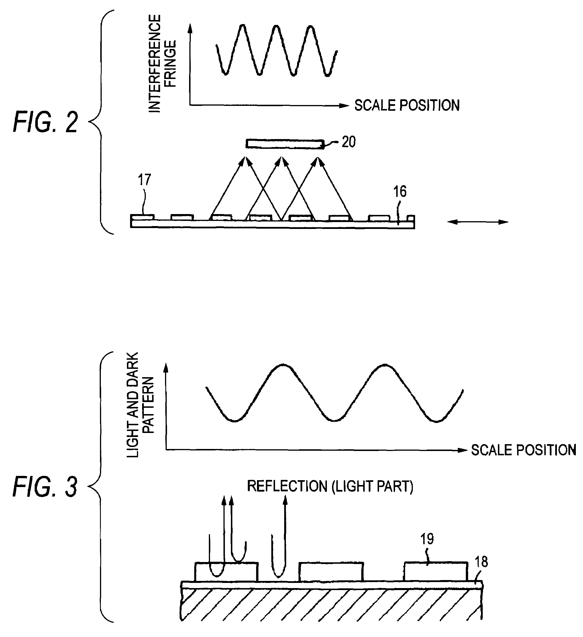
[0035]Next, FIG. 9 shows the invention applied to a reflection encoder as shown in FIG. 2.
[0036]Also in the embodiment, dirt S spreads on a transparent protective material 40 or 42 and thus the refractive power lessens and an interference fringe scarcely changes. Further, thickness t of the transparent protective material 40 or 42 is larger than the DOF and thus the effect on image formation through a lens 22 is small.
third embodiment
[0037]Next, FIG. 10 shows the invention applied to a reflection encoder as shown in FIG. 3.
[0038]Also in the embodiment, the portion of dirt S spreads and thus an interference fringe scarcely changes. Further, thickness t of a transparent protective material 40 or 42 is larger than the DOF and thus the effect on image formation through a lens 22 is small.
[0039]The transparent protective material can be implemented as a band-pass filter formed by multilayer coating by evaporation, for example, and can be provided with a function of removing external visible light, etc., for example, when an infrared light source is used.
[0040]Further, in the reflection encoder as shown in FIGS. 2 and 3, as with the first embodiment of FIG. 1, the aperture 24 may be added to the focal position of the lens 22, and in this case, since DOF lessens, the thickness t of the transparent protective material 40 or 42 can be thinned.
PUM
 Abstract
Description
Claims
Application Information
 - R&D
- Intellectual Property
- Life Sciences
- Materials
- Tech Scout
- Unparalleled Data Quality
- Higher Quality Content
- 60% Fewer Hallucinations
Browse by: Latest US Patents, China's latest patents, Technical Efficacy Thesaurus, Application Domain, Technology Topic, Popular Technical Reports.
© 2025 PatSnap. All rights reserved.Legal|Privacy policy|Modern Slavery Act Transparency Statement|Sitemap|About US| Contact US: help@patsnap.com


