Quantum dot light emitting device
a light-emitting device and quantum dot technology, which is applied in the direction of discharge tube luminescnet screens, discharge tube/lamp details, electric discharge lamps, etc., can solve the problems of high manufacturing cost, high cost and rigid substrates, and difficulty in combining multi-color output from the same chip, so as to achieve enhanced conductivity of light-emitting layers and high resolution. , the effect of enhancing the conductivity of the light-emitting layer
- Summary
- Abstract
- Description
- Claims
- Application Information
AI Technical Summary
Benefits of technology
Problems solved by technology
Method used
Image
Examples
example 1
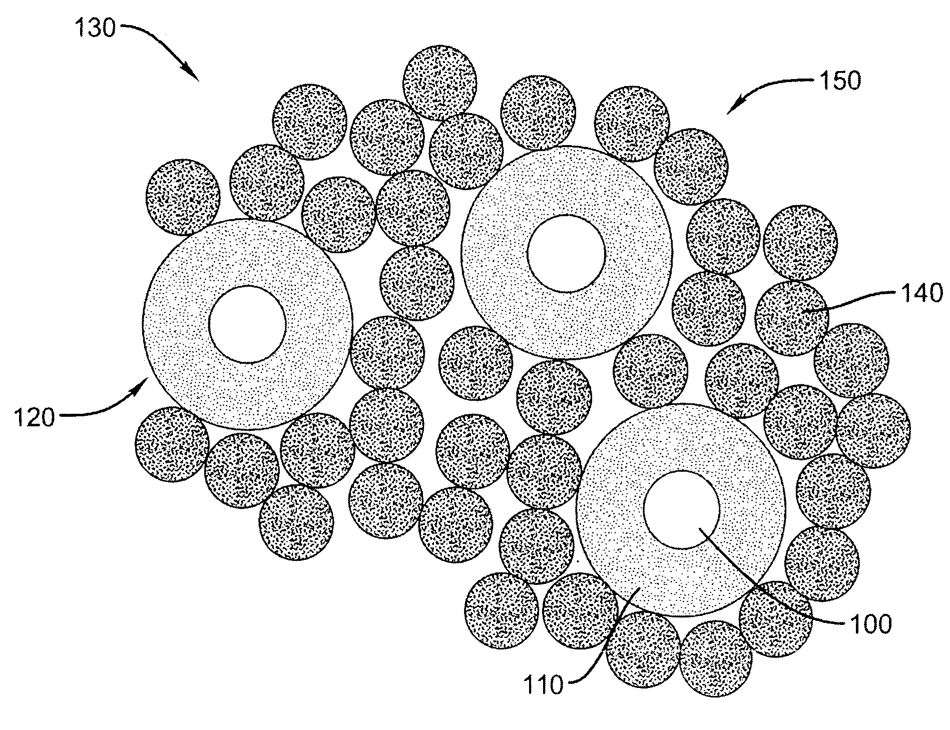
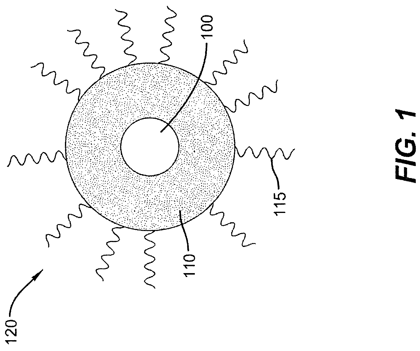
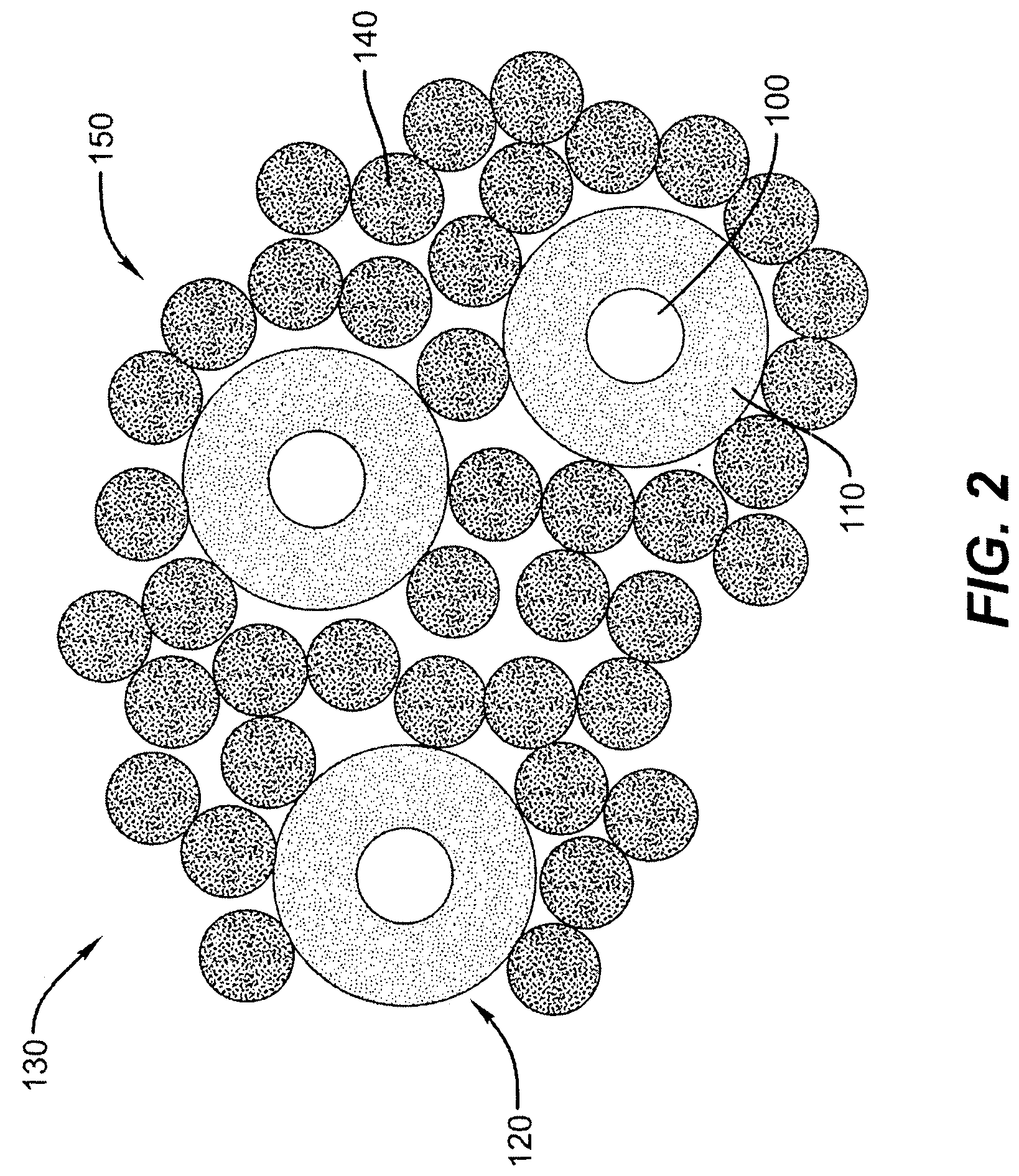
[0047]An inorganic light emitting layer 150 was formed in accordance with the schematic of FIG. 2. The inorganic nanoparticles 140 were composed of ZnS, while the core / shell quantum dots 120 had a CdSe core and a ZnSe / ZnS shell. The ZnS particles were chemically synthesized using an adaptation of the method reported by Khosravi et al. (A. A. Khosravi et al., Appl. Phys. Lett. 67, 2506 [1995]). The Zn source was ZnCl2, the sulfur source was bis(trimethlysilyl)sulfide (TMS)2S, and the surfactant / ligand was hexylamine. Butanol solutions of ZnCl2, (TMS)2S, and hexylamine, each at 0.02 M, were prepared and equal volume of each solution was used in the reaction. To prevent the oxidation of the resulting ZnS nanoparticles, the reaction was performed under inert conditions using well-known procedures. Initially, 5 ml of the zinc chloride solution and 5 ml of the hexylamine solution are combined in a two-neck flask, while vigorously stirring the mixture. Next, 5 ml of the (TMS)2S solution is...
example 2
[0051]Electroluminescent light emitting diodes were constructed using the above inorganic light emitting layer 120 as a component. ITO was sputtered onto the surface of a cleaned glass substrate 160 through a shadowmask. Following the deposition, the ITO film was annealed at 300° C. for 1 hour to improve its transparency. Next the inorganic light emitting layer 120, as described in Example 1, was deposited on the surface of the ITO. To ensure a pinhole free layer, the composite (ZnS nanoparticles and CdSe / ZnSe / ZnS core / shell / shells) colloidal dispersion was drop cast twice (each drop cast was followed by a 50 minute anneal at 270° C. in the tube furnace). Prior to the two drop casts, the deposition surface was cleaned by an acetone / methanol solvent wash, followed by blow drying the sample with nitrogen.
[0052]Next the n-type transport layer 230 was deposited. It was formed from ZnSe nanoparticles. The nanoparticles were synthesized (carried out under Schlenk line and argon flow) usin...
PUM
 Abstract
Description
Claims
Application Information
 - R&D
- Intellectual Property
- Life Sciences
- Materials
- Tech Scout
- Unparalleled Data Quality
- Higher Quality Content
- 60% Fewer Hallucinations
Browse by: Latest US Patents, China's latest patents, Technical Efficacy Thesaurus, Application Domain, Technology Topic, Popular Technical Reports.
© 2025 PatSnap. All rights reserved.Legal|Privacy policy|Modern Slavery Act Transparency Statement|Sitemap|About US| Contact US: help@patsnap.com


