
Metal matrix composite energetic structures

Active Publication Date: 2011-02-15
LOCKHEED MARTIN CORP
View PDF89 Cites 35 Cited by
  • Summary
  • Abstract
  • Description
  • Claims
  • Application Information

AI Technical Summary

Benefits of technology

[0008]According to the present invention, there is provided a munition which possesses one or more of: improved control of ballistic, thermal, structural and density characteristics, and in particular, a munition capable of delivering a significantly greater amount of total energy to the target.

Problems solved by technology

Moreover, attempts to increase the velocity of the munition often involves trade-offs in other areas which may have detrimental impacts on the overall effectiveness and / or operation of the weapon system.
However, there are engineering challenges presented by such reactive materials.
There has been a general lack of confidence in the ignition of such materials upon impact at velocities less than about 4000 ft / s.
In addition, since the above-mentioned materials are based on organic or polymeric matrix materials, which has a density less than that of most targets, i.e., steel, further acting to the detriment of penetration capabilities.
Polymeric matrix material often lacks the above-mentioned reactive fragments may not possess the desired degree of structural integrity.

Method used


Image

  • Metal matrix composite energetic structures
  • Metal matrix composite energetic structures
  • Metal matrix composite energetic structures

Examples


Embodiment Construction

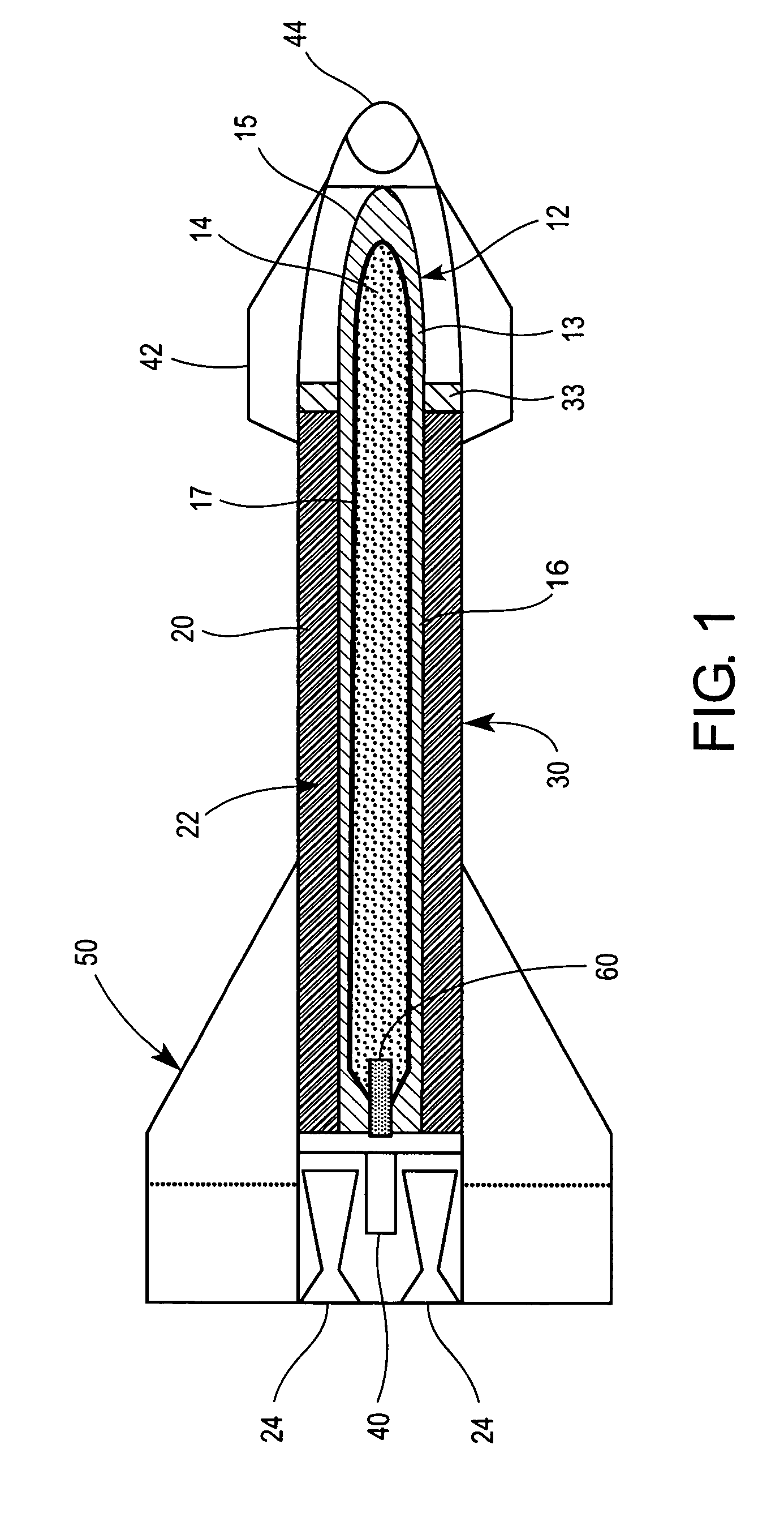
[0017]FIG. 1 illustrates a munition formed according to the principles of the present invention, and according to one embodiment thereof. The munition illustrated in FIG. 1 is in the form of a boosted penetrating bomb. The munition includes a penetrator 12 comprising a casing 13, as well as containing a payload 14, preferably in the form of an explosive medium. Optionally, a shaped charge liner or casing insert 17 may be provided within the casing 13. Other payloads may be used or included, for example, fragmenting bomblets, chemicals, incendiaries, and / or radioactive material. A rocket booster motor 20 for accelerating the penetrator 12 includes an annular fuel chamber 22 and a plurality of exhaust nozzles 24. The annular chamber 22 defines a central interior space in which the penetrator 12 is mounted.

[0018]An outer skin or shroud 30 encloses at least portions of the booster motor 20 and the penetrator 12, and provides an aerodynamic shape. The mounting structure holding the penet...


PUM


Abstract

A munition includes a structural component formed from a composite material comprising a energetic material dispersed in a metallic binder material. A method is also provided that includes forming a energetic material, combining the energetic material with a metallic binder material to form a mixture, and shaping the mixture to form a composite structural munition component.

Description

FIELD OF THE DISCLOSURE[0001]The present disclosure relates to energetic compositions for structural components of munitions. More specifically, the present disclosure relates to structural components based, at least in part, on reactive energetic materials dispersed in a metallic matrix.BACKGROUND[0002]In the discussion that follows, reference is made to certain structures and / or methods. However, the following references should not be construed as an admission that these structures and / or methods constitute prior art. Applicant expressly reserves the right to demonstrate that such structures and / or methods do not qualify as prior art.[0003]In order to maximize the destructive energy into a target, two common approaches are employed. The first approach involves the delivery of kinetic energy to a target by utilizing relatively high velocity munitions, thereby capitalizing on the sensitivity of kinetic energy (Ek) to mass (m), and especially velocity (V), as manifested by the follow...

Claims


Application Information

Patent Timeline
IPC IPC(8): F42B12/02F42B12/72F42B12/76
CPCC06B21/005C06B33/00C06B45/00C06B45/04F42B12/20F42B12/76
Inventor HUGUS, GEORGE D.SHERIDAN, EDWARD W.
Owner LOCKHEED MARTIN CORP
Learn More