
Transmission power range setting during channel assignment for interference balancing in a cellular wireless communication system

power range setting technology, applied in the field of interference balancing in a wireless communication system, can solve the problems of large intercell interference fluctuations, inaccurate dca and amc operation, and typically limited system interference, so as to reduce the large fluctuations of intercell interferen

Active Publication Date: 2011-01-25
APPLE INC
View PDF14 Cites 49 Cited by
  • Summary
  • Abstract
  • Description
  • Claims
  • Application Information

AI Technical Summary

Benefits of technology

[0033]One object of the present invention is to reduce the large intercell interference fluctuations caused by power control schemes.
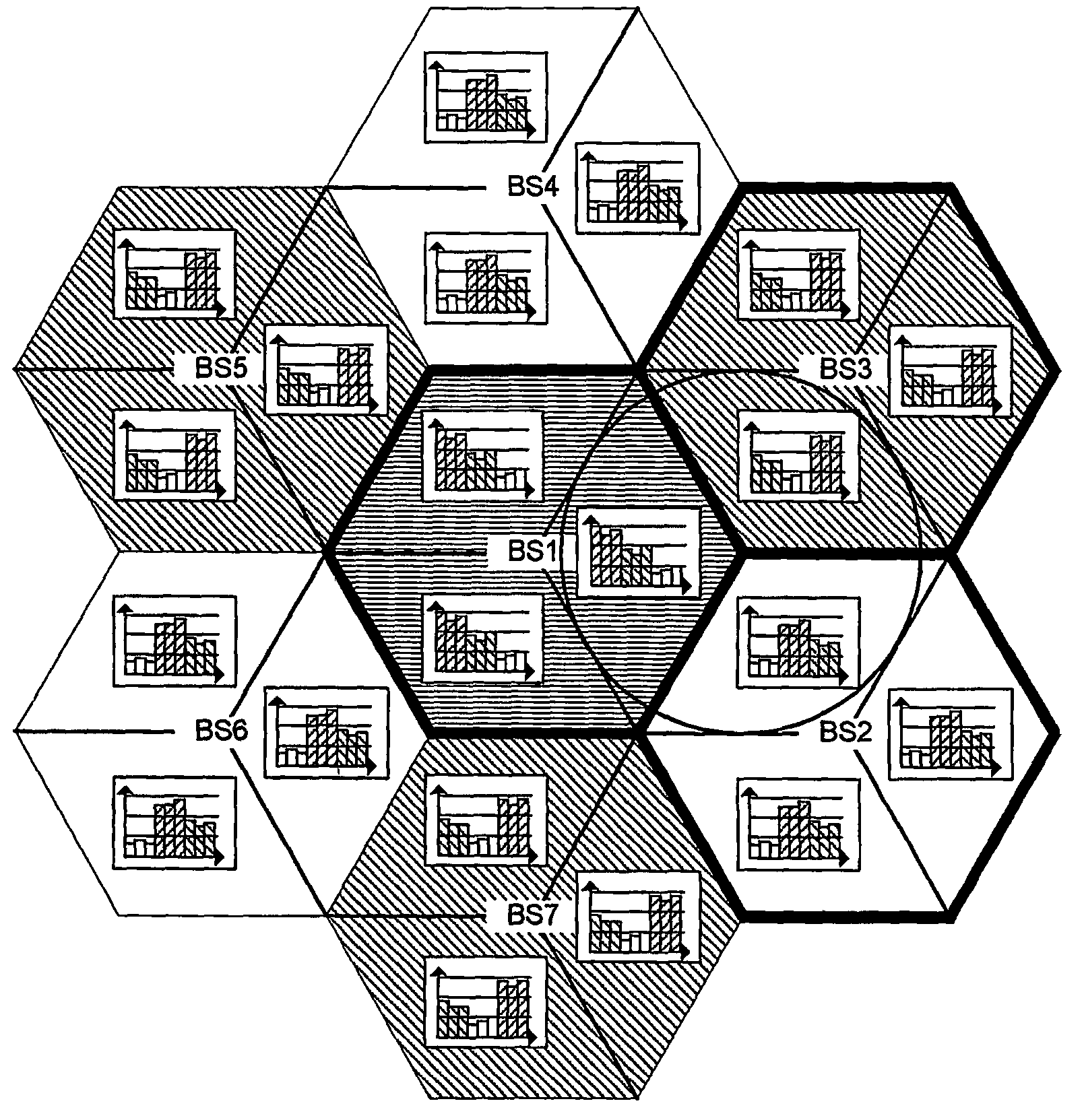
[0049]It is further noted that the different embodiments of the method for balancing the interference in a wireless communication system outlined above should not be understood as restricting the power ranges in the different cells of a cell cluster to identical power ranges. The individual power ranges in each radio cell of a cell cluster may be identical or may be different from each other. This is of advantage to be able to adapt to e.g. the respective channel conditions and / or cell-sizes in the different cells.
[0056]It is of further advantage, if the transmission power ranges in different radio cells of a cell cluster vary, such that same may be adapted to the respective channel conditions in each of the radio cells of the cell cluster.
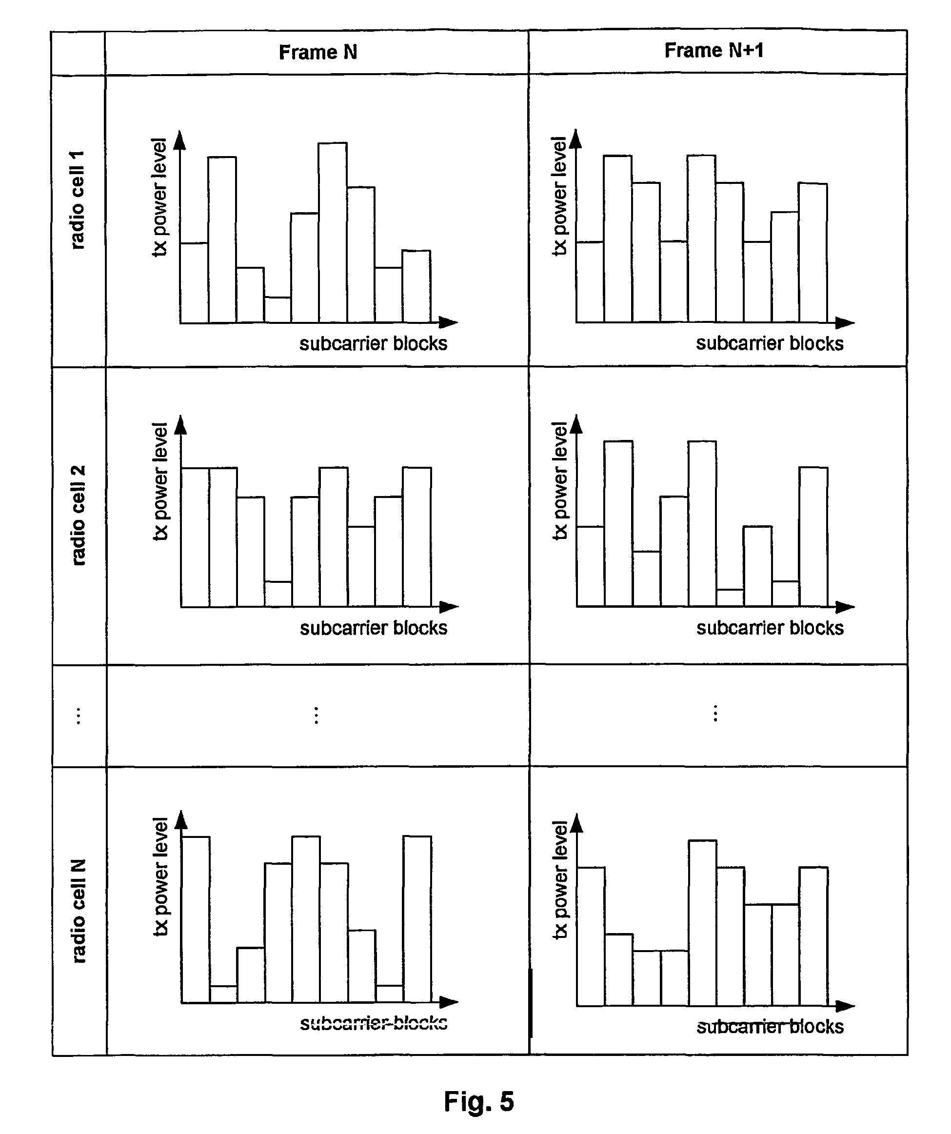
[0057]Further, the transmission power ranges in a radio cell may vary between the radio cells. As explained above, this allows individual control of the transmission power ranges in each of the cells to adapt same to changing channel quality conditions in the respective cell.

Problems solved by technology

Considering a DCA OFDMA multi-cell scenario and a frequency re-use factor of 1, the system is typically interference limited.
This delay causes inaccurate DCA and AMC operation.
The delay even increases, if the measurement is performed at the MS and needs to be fed back by signaling to the BS.
Further, there exists the so-called chicken-and-egg allocation problem: In cell A, the subcarrier block allocation and AMC can only be performed after the SIR measurement / calculation in cell A has been performed, which requires knowledge of the subcarrier block allocation in cell B (adjacent cells).
However, since the scheduling frames are in the millisecond region, the signaling would introduce additional significant delay.
Although, this increases the available throughput for those mobile stations, it can decrease the overall system throughput compared to a system, where the available power is distributed such that only non-multilevel modulation schemes (e.g. QPSK) are used.
This is caused by the reduced power efficiency of multilevel modulation schemes.
Compared to power controlled systems, for non-power controlled systems it is more likely that mobile stations in low geometry cannot receive any data with single transmission attempts, but would need several retransmissions.
Therefore, the average number of transmissions (ARQ retransmissions) increases, which in turn increases the transmission delay and feedback signaling, as well as decreasing the bandwidth efficiency.
This results in a burstier subcarrier block allocation.
This will make the SIR estimation according to equation (2) more difficult, since the subcarrier block allocation changes more often.
Note however, the slow PC can only operate within certain limits (dynamic range of the control commands), i.e. the power compensation might not be sufficient or fast enough for any link.
With slow / fast PC the instantaneous SIR estimation / measurement / calculation problem as outlined in the previous sections above, is more severe compared to the non-PC case.

Method used


Image

  • Transmission power range setting during channel assignment for interference balancing in a cellular wireless communication system
  • Transmission power range setting during channel assignment for interference balancing in a cellular wireless communication system
  • Transmission power range setting during channel assignment for interference balancing in a cellular wireless communication system

Examples


Embodiment Construction

[0096]In the following the present invention will be described with regard to wireless communication system using OFDM. Though the examples relate to OFDM, it should be noted that the ideas underlying the present invention may be readily applied to other FDM based communication systems as well.

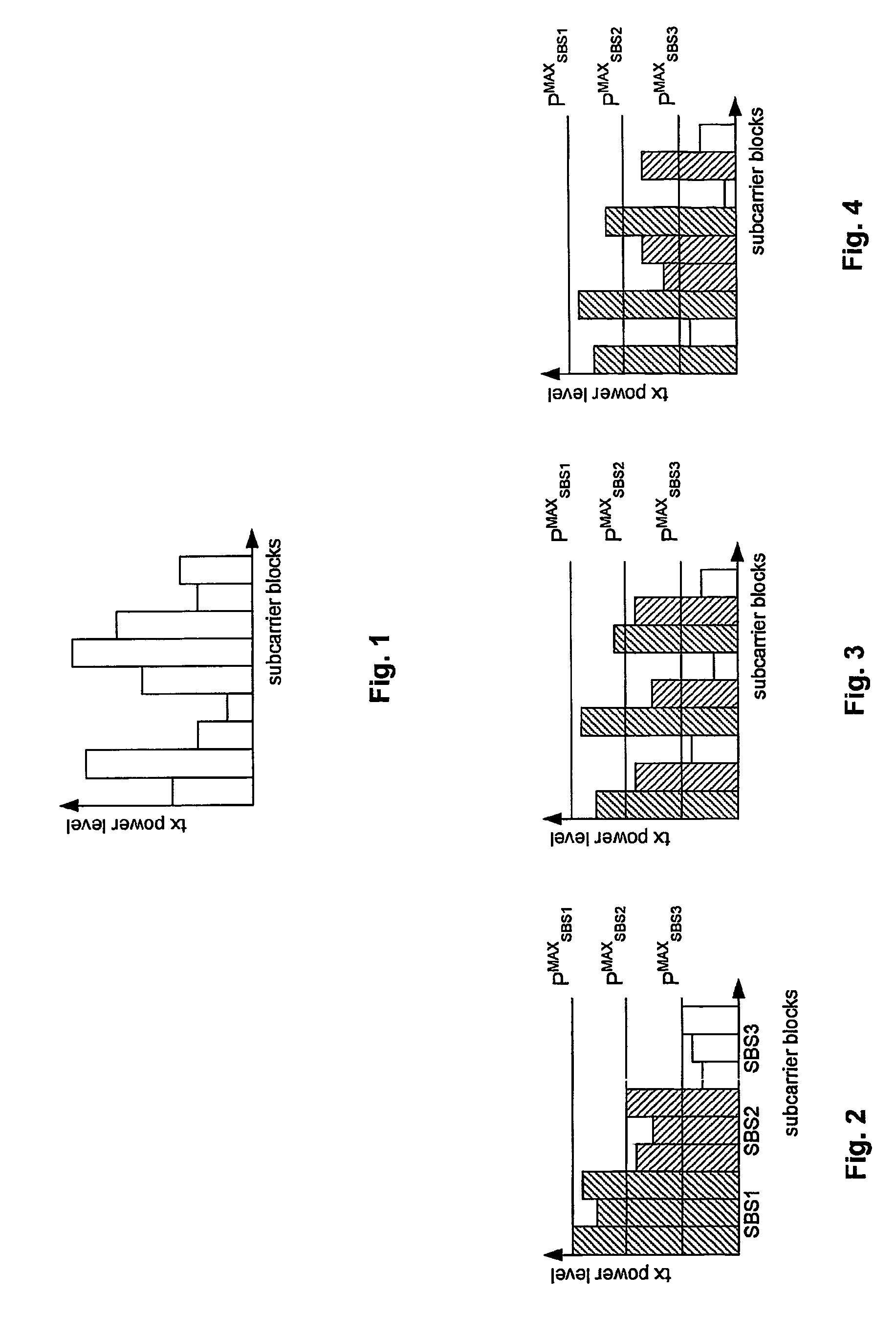
[0097]According to an embodiment of the present invention the OFDM subcarrier blocks may be divided into N subcarrier block-sets (SBS). FIG. 1 shows the distribution of transmission power for subcarrier blocks according to a prior art system. FIGS. 2, 3 and 4 show three examples for the distribution of power limits (or ranges) with different SBS definitions according to different embodiments of the present invention. The assignment of the power limits may be performed in accordance with the SBS power limits in adjacent cells in order to control the SIR levels depending on the SBS as e.g. shown in FIGS. 8, 9 and 10.

[0098]Compared to prior art, this power-limit definition has the advantage that ...


PUM


Abstract

The present invention relates to a method for balancing the distribution of interference between radio cells in a wireless communication system comprising cells in which subcarrier blocks are used for communication. A number of adjacent cells build a cell cluster. Moreover, the present invention relates to a corresponding method adapted for use in a system in which multi beam antennas or multiple antennas are used. Furthermore, the present invention relates to base stations performing the above method as well as a communication system comprising the base stations. To reduce the large average SIR variations without causing additional SIR estimation, measurement and calculation problem as introduced with power control the invention suggests to group subcarrier blocks into a plurality of subcarrier block sets in each cell of a cell cluster, to determine transmission power ranges for each of the cells of said cell cluster, and to assign transmission power ranges to the subcarrier block sets to perform TPC within the ranges.

Description

FIELD OF THE INVENTION[0001]The present invention relates to a method for balancing the distribution of interference between radio cells in a wireless communication system. The system comprises a plurality of radio cells in which a plurality of subcarrier blocks is used for communication, wherein each subcarrier block comprises a plurality of subcarriers. Further, a number of adjacent radio cells build a cell cluster. Moreover, the present invention relates to a corresponding method adapted for use in a system in which sectorized base stations are used. Furthermore, the present invention relates to base stations performing the above method as well as a communication system comprising the base stations.BACKGROUND ART[0002]In modern packet-based cellular mobile communication systems, Dynamic Channel Assignment (DCA) schemes are popular, since they are an efficient tool to increase the (air interface) system throughput. DCA schemes utilize the short term fluctuations (fast fading) of t...

Claims


Application Information

Patent Timeline
Patent Type & Authority Patents(United States)
IPC IPC(8): H04W40/00H04B1/00H04B15/00H04W72/00H04B17/00H04W52/32H04B7/005H04B7/04H04J13/00H04W52/00H04W52/26H04W52/34H04W52/36H04W52/42H04W52/50
CPCH04W52/262H04W52/367H04W52/42H04W52/50H04W52/34
Inventor WENGERTER, CHRISTIANVON ELBWART, ALEXANDER GOLITSCHEK EDLER
Owner APPLE INC
Learn More