
Ink set and image forming apparatus and method

a technology of image forming apparatus and ink set, which is applied in the direction of recording apparatus, ink apparatus, instruments, etc., can solve the problems of difficult to achieve high quality on the intermediate transfer body, achieve good transfer characteristics, and no ink and image recording, etc., to achieve free, prevent density non-uniformities, and high quality

Active Publication Date: 2011-01-25
FUJIFILM CORP
View PDF3 Cites 30 Cited by
  • Summary
  • Abstract
  • Description
  • Claims
  • Application Information

AI Technical Summary

Benefits of technology

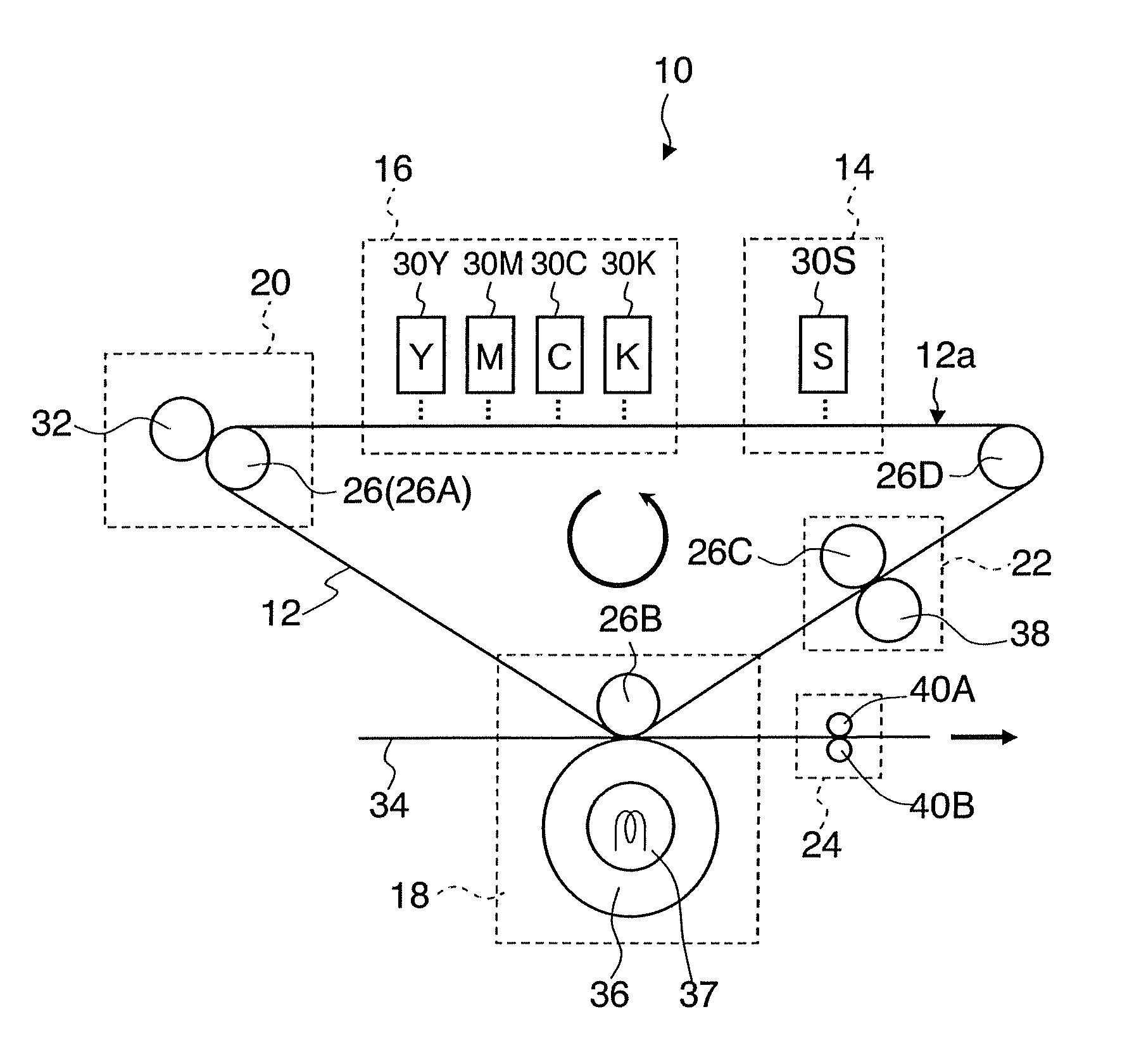
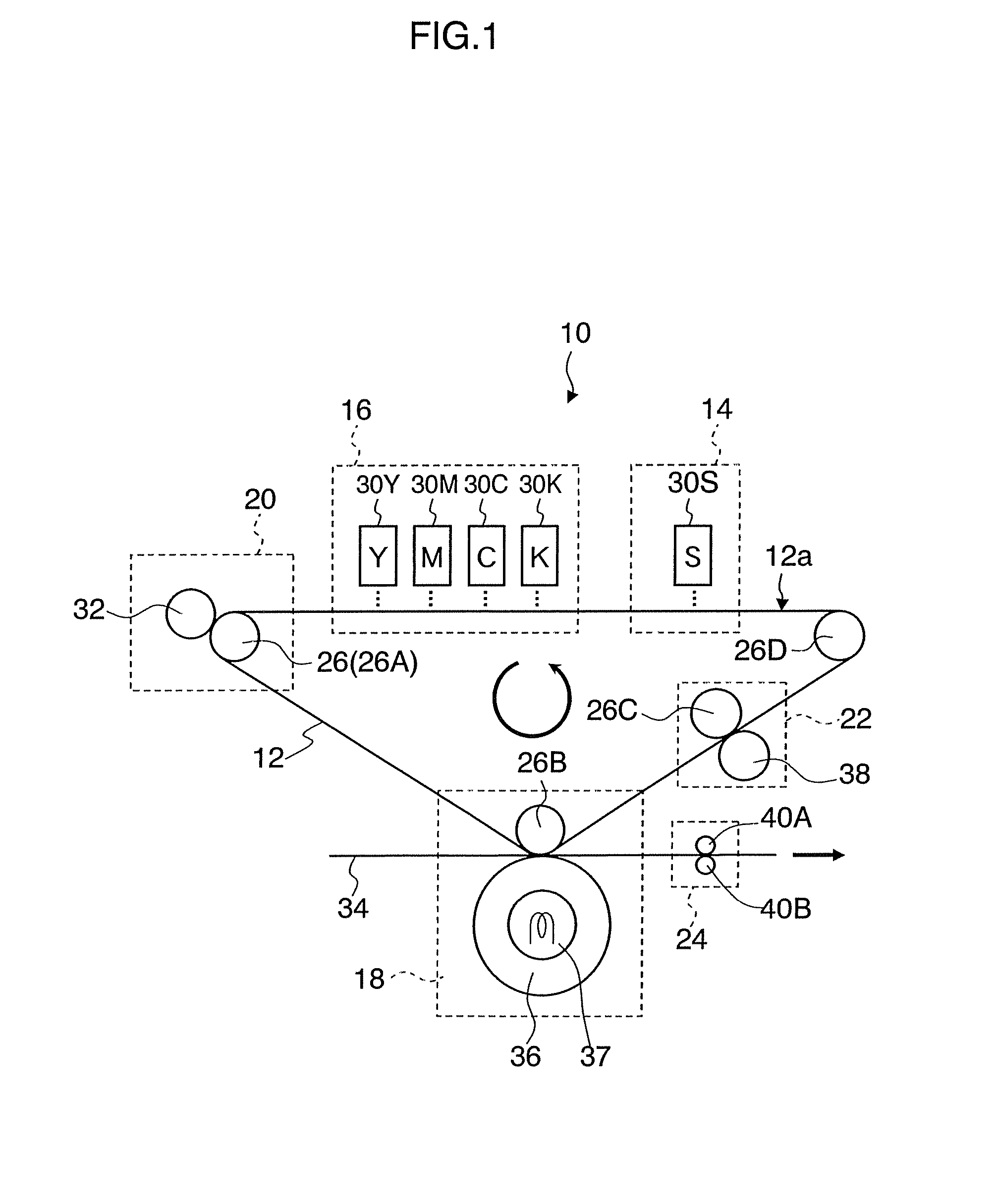
The present invention has been contrived in view of these circumstances, an object thereof being to provide an ink set, and an image forming apparatus and method whereby a high-quality image which is free of ink bleeding can be obtained, while being able to prevent density non-uniformities in solid image regions. Moreover, a further object of the present invention is to provide an ink set, and an image forming apparatus and method, whereby it is possible to prevent transfer defects and transfer non-uniformities in an intermediate transfer type of recording method, and it is also possible to obtain a high-quality image which is free of ink bleeding, as well as preventing density non-uniformities in solid image regions.
According to the present invention, it is possible to provide an ink set, and an image forming apparatus and method whereby a high-quality image which is free of ink bleeding can be obtained, while being able to prevent density non-uniformities in a solid image region.

Problems solved by technology

However, in the field of industrial printing, it is essential to achieve high-speed operation, from the viewpoint of productivity, but there have been no ink and image recording method which enables high-quality prints of the level of a silver halide print to be produced at high speed.
In the image forming apparatus of intermediate transfer type, it has been difficult to achieve high quality on the intermediate transfer body as well as achieving good transfer characteristics.
This is because a liquid flow is created on the intermediate transfer body and the image quality is liable to decline as a result of this flow.
However, although Japanese Patent Application Publication No. 2001-30616 and Japanese Patent Application Publication No. 2002-52804 provide effective methods for obtaining an image with high-resolution and high-quality up to a certain degree, they are problematic in that the ink bleeding is liable to occur in image border sections, and that density non-uniformities are liable to occur in the case of a solid image.
Consequently, there exist portions where the aggregating action acts too strongly and portions where the reaction is insufficient.
However, since this technology utilizes the aggregating action similar to the one as in Japanese Patent Application Publication Nos. 2001-30616 and 2002-52804, then non-uniformities of the reaction occur in the image forming region, and therefore variations in the aggregating force are liable to arise.
Consequently, transfer non-uniformities and transfer defects occur, and there is a possibility that the quality of the image formed on the recording medium will be seriously impaired.
Furthermore, since unreacted coloring material is liable to remain, then the coloring material flows (moves) on the transfer body, and the image quality at the stage of forming an image on the intermediate transfer body cannot be regarded as adequate.
Moreover, Japanese Patent Application Publication No. 2006-83277 indeed has the effect of promoting the aggregation of the coloring material due to the aggregating effect of the polymer particles as a result of the change in the pH of the ink, but, depending on the form (or extent of aggregation) of aggregation of the polymer particles, a problem may arise in that satisfactory effects of achieving high image quality such as effects of the suppression of the ink bleeding or the suppression of density non-uniformities, or the like cannot be obtained.

Method used


Image

  • Ink set and image forming apparatus and method
  • Ink set and image forming apparatus and method
  • Ink set and image forming apparatus and method

Examples


examples

The present invention is described in more specific terms below with reference to practical examples.

Practical examples of the present invention will be described below, but the present invention is not limited to these.

The ink (first liquid) and the treatment liquid (second liquid) used for carrying out the present invention were prepared. The ink and the treatment liquid prepared have the compositions described below.

Furthermore, a sample liquid (aqueous polymer solution) was prepared separately by adding polymer particles to the ink solvent component, in order to investigate the change in the volume-average particle size and the zeta potential of the polymer particles along with a pH change of the sample liquid (aqueous polymer solution).

Ink

(Manufacture of Pigment Dispersion)

The components listed below were mixed in the composition as shown below so that the total quantity was 500 parts by weight, and 2,2′-Azobis(2,4-dimethyl)valeronitrile of 2 parts by weight was added as a poly...


PUM

PropertyMeasurementUnit
Diameteraaaaaaaaaa
Nanoscale particle sizeaaaaaaaaaa
Acidityaaaaaaaaaa

Abstract

The ink set includes: a first liquid which contains a coloring material, a polymer, and a dispersion medium composed of water and water-soluble solvent, the coloring material and the polymer being dispersed in the dispersion medium, the coloring material having properties such that when dispersed in an aqueous coloring material solution, a volume-average particle size of the coloring material is changed along with a pH change of the aqueous coloring material solution, the polymer having properties such that when dispersed in an aqueous polymer solution, a volume-average particle size of the polymer is changed along with a pH change of the aqueous polymer solution; and a second liquid which changes pH of the first liquid, wherein a condition of |α−β1|≧|α−β2| is satisfied, where α is pH of the first liquid before the first liquid is subjected to a pH change caused by the second liquid, β1 is pH of the aqueous coloring material solution at which the volume-average particle size of the coloring material reaches 1000 nm along with the pH change of the aqueous coloring material solution, and β2 is pH of the aqueous polymer solution at which the volume-average particle size of the polymer reaches 1000 nm along with the pH change of the aqueous polymer solution.

Description

BACKGROUND OF THE INVENTION1. Field of the InventionThe present invention relates to an ink set, and an image forming apparatus and method, and more particularly, to an ink set including two liquids, and an image forming apparatus and method using this ink set.2. Description of the Related ArtWith the rapid progress of inkjet technology and digital cameras and other digital imaging technology in recent years, it has become possible to obtain high-quality photographic prints which surpass silver halide photographs, easily, even in a general domestic situation. On the other hand, inkjet technology has started to be adapted for and applied to many diverse fields, such as industrial printing. However, in the field of industrial printing, it is essential to achieve high-speed operation, from the viewpoint of productivity, but there have been no ink and image recording method which enables high-quality prints of the level of a silver halide print to be produced at high speed. Therefore, r...

Claims


Application Information

Patent Timeline
IPC IPC(8): B41J2/325C09D11/02B41J2/01B41M5/00C09D11/00C09D11/322C09D11/38C09D11/54
CPCB41M5/0017B41M5/0256C09D11/40C09D11/54B41M5/0047B41M5/0058B41M5/0064B41M5/007B41M5/0076B41M7/0018
Inventor HOUJOU, HIROAKI
Owner FUJIFILM CORP
Learn More