
Method of making an ice dispense agitator

a technology of agitator and agitator body, which is applied in the direction of wind motor components, non-positive displacement fluid engines, liquid fuel engine components, etc., can solve the problem that the assembly of agitator can be relatively expensive to manufacture, and achieve the effect of convenient and inexpensive fabrication

Inactive Publication Date: 2011-01-25
IMI COMELIUS
View PDF10 Cites 4 Cited by
  • Summary
  • Abstract
  • Description
  • Claims
  • Application Information

AI Technical Summary

Benefits of technology

"The present invention provides a method for making an ice dispense agitator that is easy and inexpensive to manufacture, using flat metal stock and minimal welding. The method involves cutting a unitary agitator body from flat metal stock and bending the ice sweeping arms and agitating blade to desired configurations. The resulting agitator is strong and durable, with minimal breakage and damage during use. The method can be performed using laser cutting, plasma cutting, milling, sawing, stamping, die cutting, or computer numeric controlled machine punching. The agitator can be easily and inexpensively fabricated, with the end edge of the ice sweeping arms and the at least one agitating blade being welded together. The agitator has a unique design that allows for efficient ice dispensing and durability."

Problems solved by technology

Due to the plurality of ice breaking and sweeping arms, agitator assemblies can be relatively expensive to manufacture, in that they require the welding together of various separate components.

Method used


Image

  • Method of making an ice dispense agitator
  • Method of making an ice dispense agitator
  • Method of making an ice dispense agitator

Examples


Embodiment Construction

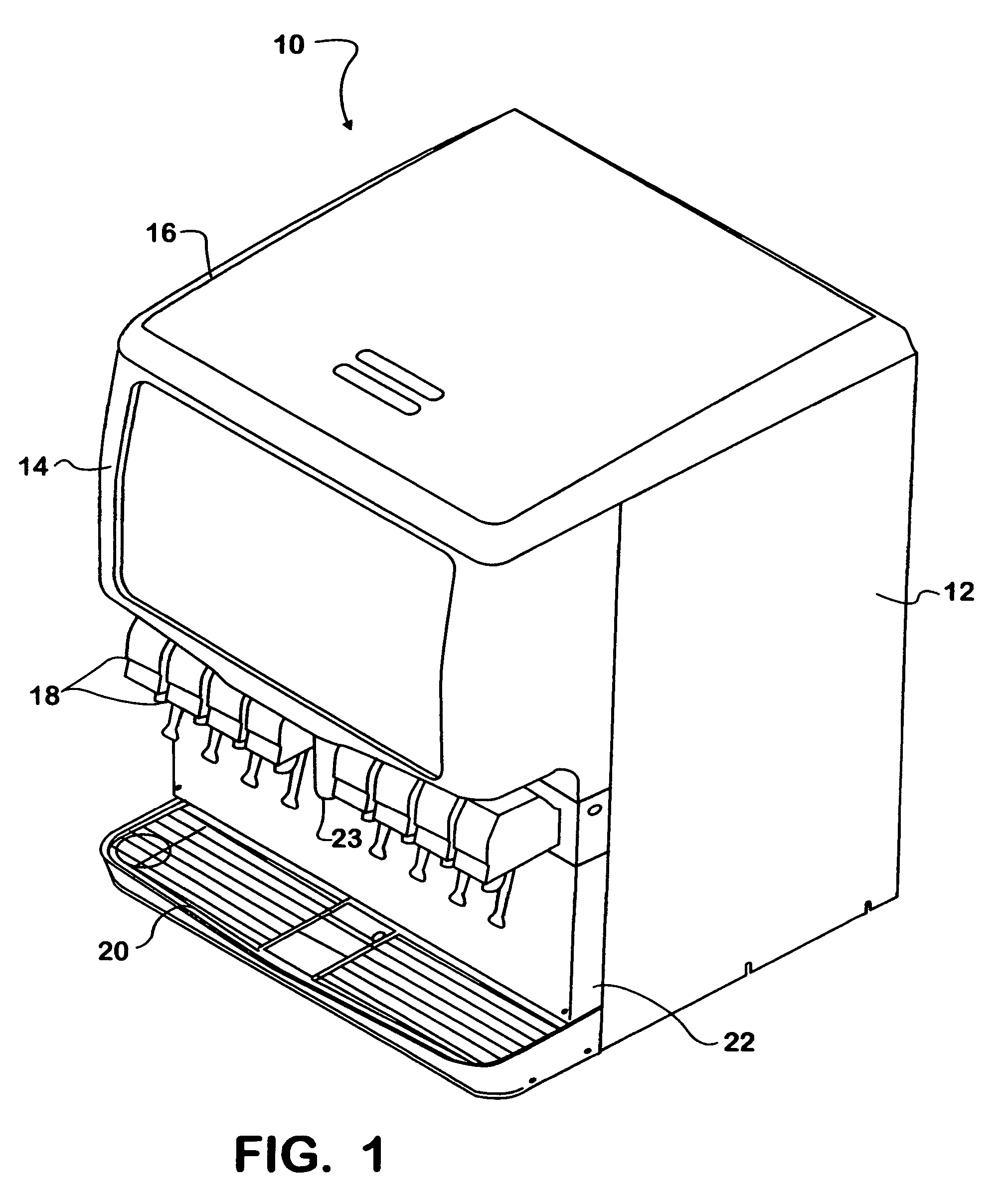
[0016]The present invention provides an improved method of making an ice dispense agitator or auger that is particularly adapted for use in a combined ice and beverage dispensing machine of the general type shown in FIG. 1 and indicated generally at 10. As is conventional, the ice / beverage dispenser 10 includes an outer housing 12, a merchandising cover 14 and an ice bin cover 16 that is removable to open the top of the bin for filling of the bin with ice. A plurality of beverage dispensing valves 18 are secured to a front surface of the dispenser 10 above a drip tray 20 and adjacent to a splash panel 22. An ice dispensing chute 23 is also secured to the front surface of the dispenser centrally of the beverage dispensing valves 18 and above the drip tray 20.

[0017]With reference to FIG. 2, the ice / beverage dispenser 10 also includes a hopper or bin 24 defining therewithin an ice retaining compartment 25. A cold plate 26 is located in a lower compartment 27 beneath the ice bin 24, and...


PUM

PropertyMeasurementUnit
angleaaaaaaaaaa
angleaaaaaaaaaa
axis of rotationaaaaaaaaaa

Abstract

A method of making an ice dispense agitator of a type as may be used in ice and beverage dispensing machines is characterized by manufacturing the agitator as an integral unit by cutting the agitator from flat metal stock and then bending the agitator into a desired final shape.

Description

[0001]This application is a continuation-in-part of application Ser. No. 10 / 812,370, filed Mar. 29, 2004 now abandoned, and claims benefit of provisional application Ser. No. 60 / 462,163, filed Apr. 10, 2003.BACKGROUND OF THE INVENTION[0002]The present invention relates generally to ice dispensing equipment, and in particular to ice dispensing equipment utilizing a rotating agitator for moving and dispensing the ice.[0003]Ice dispensing equipment is well known and generally employs an ice retaining bin and an ice chute that is placed in communication with ice in the bin through an electrically operated gate. Ice is dispensed from the bin by opening the gate for a flow of ice from the bin into, through and out of the chute into a suitable receptacle, such as a cup for a beverage. Ice dispensing is typically initiated by actuation of a switch that operates an electrically driven dispensing mechanism that includes and opens the gate, usually until the switch is de-actuated. Also known i...

Claims


Application Information

Patent Timeline
Patent Type & Authority Patents(United States)
IPC IPC(8): B01F7/00B02C17/20B02C1/10B21D53/78B63H1/26B21K25/00F25C5/00
CPCF25C5/007Y10T29/49798Y10T29/49789Y10T29/49316Y10T29/49325F25C5/24
Inventor TOBLER, ANDREW J.
Owner IMI COMELIUS
Learn More