
System and method for using a capacitive door edge sensor

a capacitive door edge and sensor technology, applied in the direction of motor/generator/converter stopper, dynamo-electric converter control, instruments, etc., can solve the problems of previous systems not being able to detect obstructions and may exist obstructions, and achieve easy and inexpensive fabrication, false obstruction readings, and increased capacitance

Active Publication Date: 2008-09-02
THE CHAMBERLAIN GRP INC
View PDF18 Cites 5 Cited by
  • Summary
  • Abstract
  • Description
  • Claims
  • Application Information

AI Technical Summary

Benefits of technology

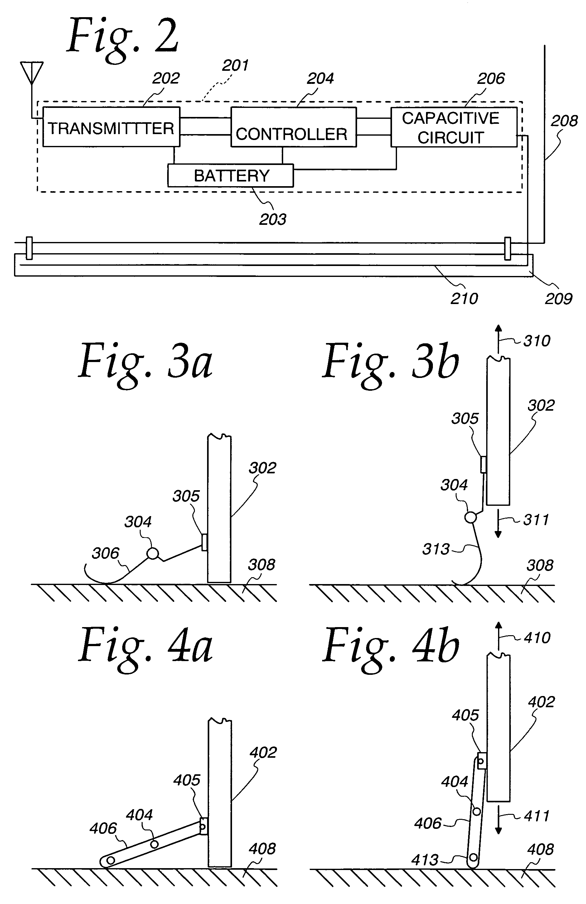
[0006]A system and method for determining whether an obstruction is present in the pathway of a movable barrier avoids false detections of obstructions. As a conductive member on the edge of the moveable barrier approaches the ground, a post or some other reference object, the capacitance between the conductive member and its ground is measured. This measured value is maintained at a substantially constant value or held below a threshold as the conductive element approaches the reference. The approach is easy and inexpensive to implement on current moveable barrier systems.
[0010]Thus, a system and method is provided whereby the capacitance sensed between the conductive member and its ground is maintained at a substantially constant value. Since the capacitance as measured between the conductive member and its ground remains substantially constant (in the absence of a real obstruction), false obstruction readings are avoided. In addition, the sensed capacitance does not have to be altered by the system to take into account the increase in capacitance as the conductive member approaches a reference, such as the physical ground. Furthermore, the system can be easily and inexpensively fabricated and applied to current moveable barrier systems.

Problems solved by technology

Obstructions may exist or may enter the pathway of the moveable barrier.
Thus, these previous systems could not be used to detect an obstruction unless the readings were sufficiently adjusted to take into account the detection of the ground or other reference.

Method used


Image

  • System and method for using a capacitive door edge sensor
  • System and method for using a capacitive door edge sensor
  • System and method for using a capacitive door edge sensor

Examples


Embodiment Construction

[0017]For illustrative purposes, the following description refers to a moveable barrier that is a garage door. However, it will be understood by those skilled in the art that the moveable barrier may not only be a garage door but may be any type of barrier such as a fire door, shutter, window, gate. Other examples of barriers are possible.

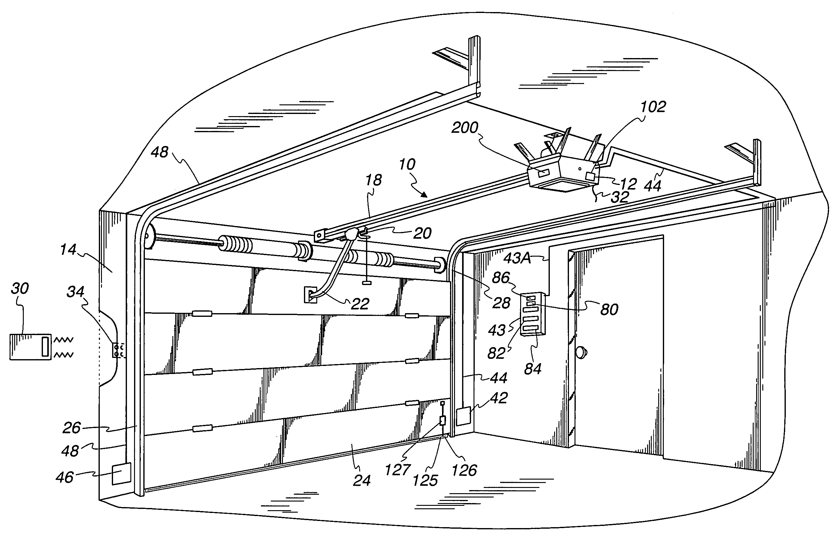
[0018]Referring now to the drawings and especially to FIG. 1, a movable barrier operator, which is a garage door operator, is generally shown therein and includes a head unit 12 mounted within a garage 14. More specifically, the head unit 12 is mounted to the ceiling of the garage 14 and includes a rail 18 extending there from with a releasable trolley 20 attached having an arm 22 extending to a multiple paneled garage door 24 positioned for movement along a pair of door rails 26 and 28. The system includes a hand-held transmitter unit 30 adapted to send signals to an antenna 32 positioned on the head unit 12 as will appear hereinafter. An external...


PUM


Abstract

A system and method for sensing capacitance at the edge of a movable barrier and for detecting an obstruction includes positioning a conductive member within or about a holder. A sensed capacitance between the conductive member and ground. A controller is coupled to the sensor. The controller determines whether an obstruction exists within a path of the barrier by analyzing the sensed capacitance. The conductive member and holder move away from a physical reference as the physical reference is approached such that the sensed capacitance between the conductive member and the physical reference remains below a predetermined threshold.

Description

FIELD OF THE INVENTION[0001]The field of the invention generally relates to methods and devices for controlling movable barrier operators. More specifically, the invention relates to detecting obstructions in the pathways of moveable barriers.BACKGROUND OF THE INVENTION[0002]Barrier movement operators are automated systems which are used to move a barrier with respect to an opening. Examples of barriers to be moved include garage doors, gates, fire doors and rolling shutters. A number of barrier movement operators have been sold over the years most of which include a head unit containing a motor connected to a transmission. The transmission, which may include, for example, a belt drive, a chain drive, a screw drive or extendible arm is then coupled to the barrier for opening and closing.[0003]Such barrier movement operators also typically include a wall control unit, which is connected to send signals to the head unit thereby causing the head unit to open and close the barrier. In a...

Claims


Application Information

Patent Timeline
Patent Type & Authority Patents(United States)
IPC IPC(8): G05B5/00H02H7/08H02P1/04H02P3/00H02P7/00E05F15/00E05F15/16E06B9/88H03K17/955
CPCE06B9/88H03K17/955E05F15/46E05Y2201/47E05Y2400/822E05Y2600/13E05Y2600/45E05Y2800/40E05F15/668H03K2217/960755E05F15/00E05Y2900/106E05Y2900/00H03K17/975
Inventor FITZGIBBON, JAMES J.
Owner THE CHAMBERLAIN GRP INC
Learn More