
Image processing device, image processing method, program, storage medium and integrated circuit

a technology of image processing and image processing method, which is applied in the field of image processing methods, image processing devices, programs, storage media, and integrated circuits, can solve the problems of large degree of dependence on image, increased cost of special devices, and prone to impact on the precision with which the threshold is determined, so as to enhance the feeling of depth and improve the feeling of depth

Inactive Publication Date: 2011-01-11
SOVEREIGN PEAK VENTURES LLC
View PDF5 Cites 19 Cited by
  • Summary
  • Abstract
  • Description
  • Claims
  • Application Information

AI Technical Summary

Benefits of technology

"The invention is an image processing device that uses depth information to enhance the feeling of depth in images. The device calculates color information from an image signal and adjusts the color information based on the depth information. This results in a more immersive experience for the viewer. The device can adjust the correction gain based on the depth information to make the foreground or background of a pixel more noticeable. The device also includes a color characteristic calculation and a correction amount control to adjust the color information based on the depth information. Overall, the invention improves the overall depth perception of images."

Problems solved by technology

In response, three-dimensional televisions and the like that utilize the binocular parallax of humans have been proposed, but it has been pointed out that special dedicated glasses are often required, that there is a large degree of dependence on the image, and that the special devices that are required increase costs.
For this reason, the precision with which the threshold is determined is prone to impact this.
In the case of originally high resolution image data, the drop in resolution caused by this blurring has a significant impact on the picture quality.
Further, with the image processing method of the second conventional example, the determination of foreground or background is performed only for border portions that have a sufficiently large differential value, and thus the determination of foreground and background is not performed on weak border portions such as texture patterns or on border portions that cannot be suitably extracted due to the image capturing conditions, such as the ambient outside light.
Further, since threshold processing is performed on the 2nd-order differential signal of pixels that are believed to be in the border in order to determine whether they are foreground or background, the threshold determination precision is also prone to have an impact when determining depth information as well.
Thus, there is a risk that objects with the same border and at the same distance may have both strongly enhanced and weakly enhanced edges, and there is also a risk that areas where the luminance is not continuous may occur due to only strong edge enhancement and weak edge enhancement being performed at the border portions.
It is not possible to determine whether the 2nd-order differential signal of the luminance is small as the result of blurring caused by the conditions under which the image was captured (focal point shifting or movement) or due to the interpolation that is performed when simply transforming a low resolution image to a higher resolution, or whether that pixel is actually in the background region.
For this reason, for example, in the case of decoding an image that has been encoded with an irreversible encoding method and then removing distortion in the decoded image with a low-pass filter or the like, the entire image may be determined to be background, depending on the setting for the threshold determination value of the 2nd-order differential signal, and there is a danger that conventional edge processing will not be carried out appropriately.

Method used


Image

  • Image processing device, image processing method, program, storage medium and integrated circuit
  • Image processing device, image processing method, program, storage medium and integrated circuit
  • Image processing device, image processing method, program, storage medium and integrated circuit

Examples


first embodiment

[0221]First, an image processing method and an image processing device 100 for correcting the color information of a pixel according to the depth information are described as a first embodiment of the invention using FIGS. 1 through 10.

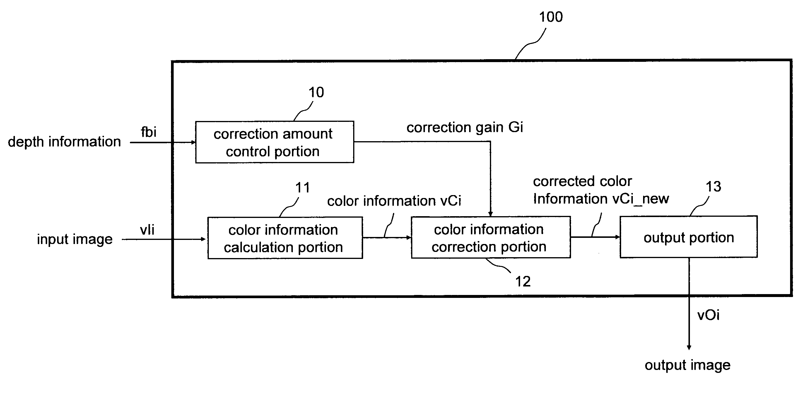
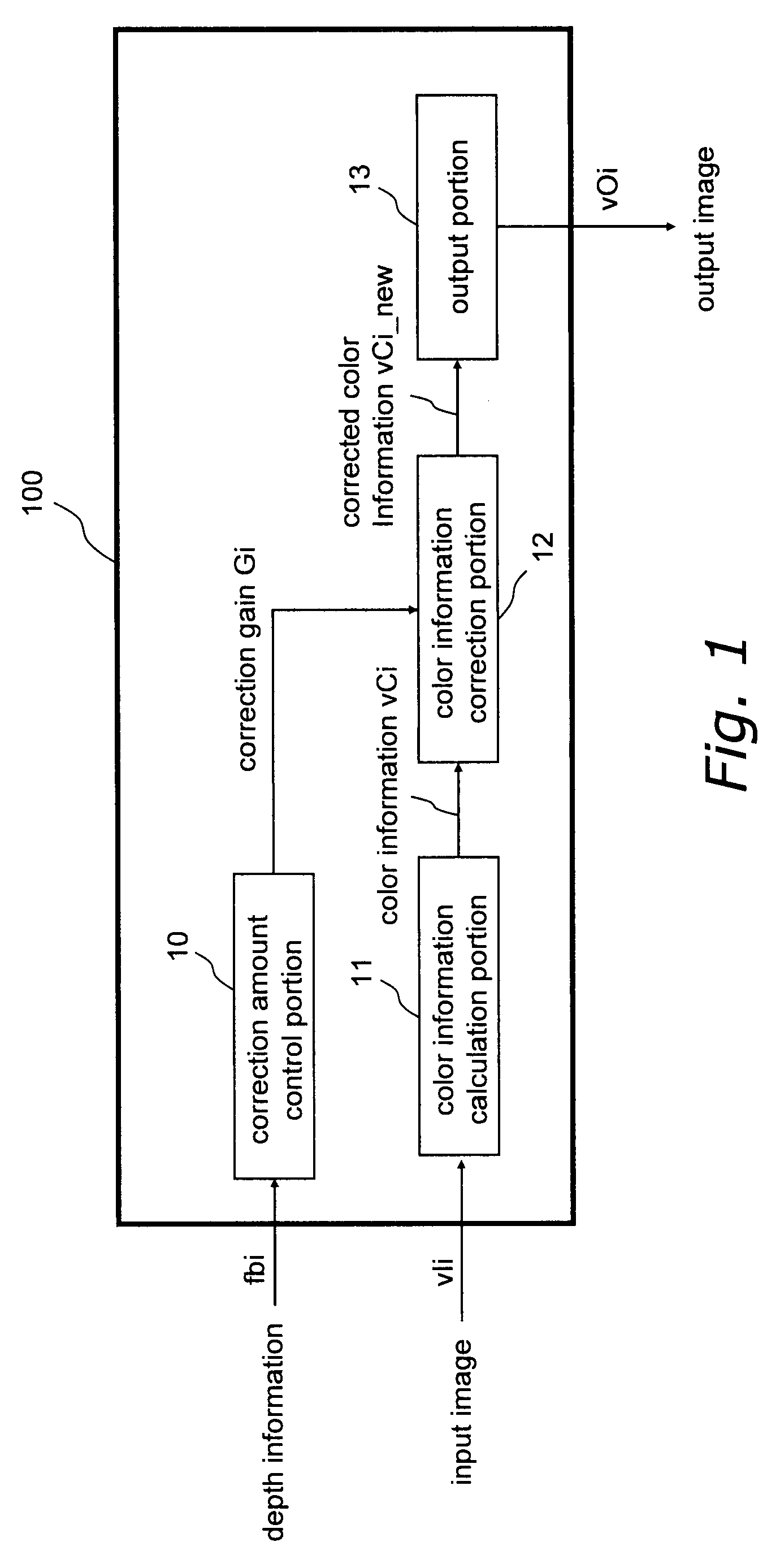
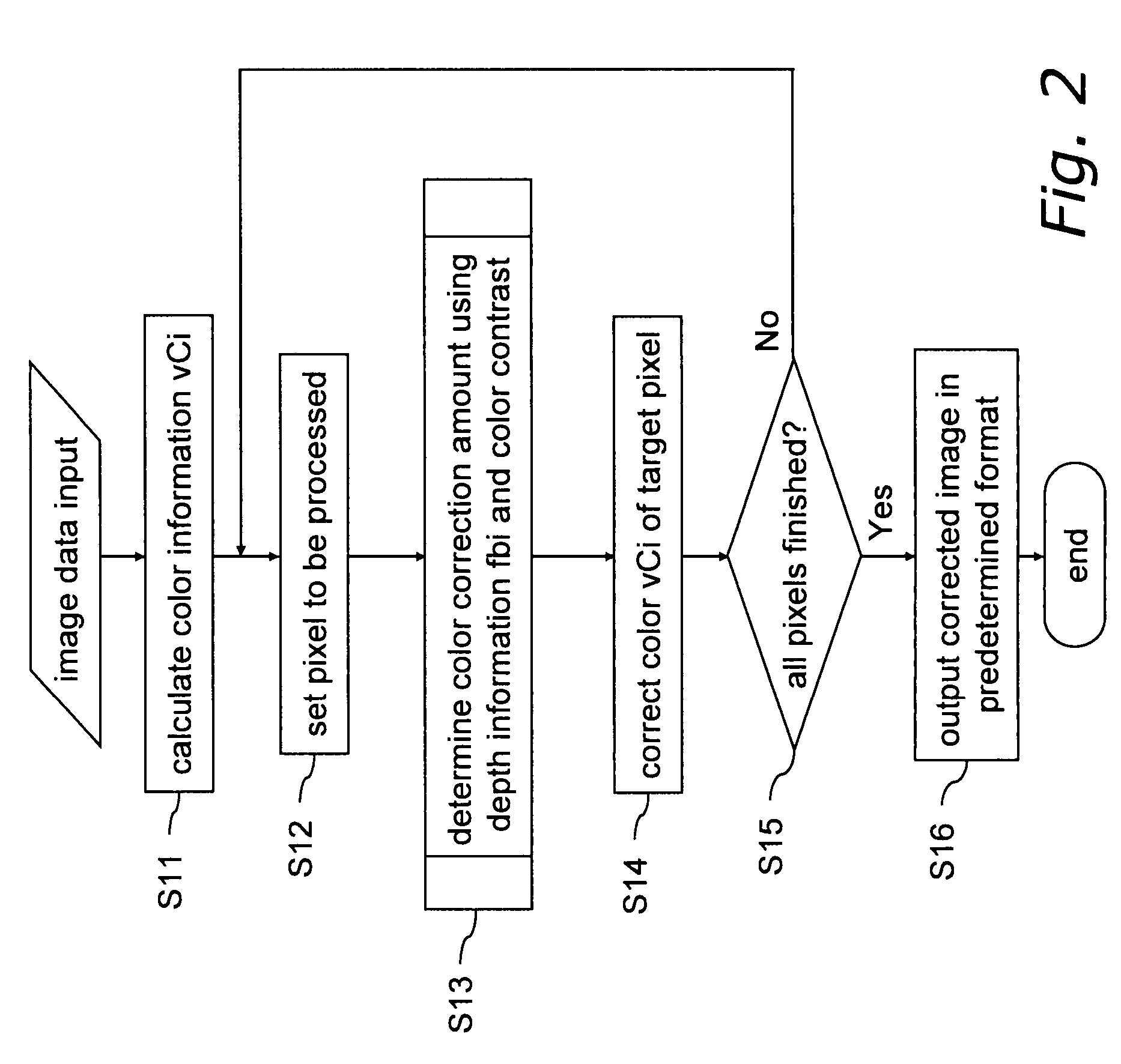
[0222]FIG. 1 shows the configuration of the image processing device 100 according to the first embodiment. FIG. 5 shows the configuration of a color information correction portion 12. FIG. 2 shows a process flowchart of the image processing method of the first embodiment. FIG. 6 shows a flowchart of the color correction portion and a flowchart of color contrast amount data calculation.

[0223]The invention is a device that corrects color information in an image by processing the image data, and for example can be installed in image-capturing devices such as digital still cameras and digital video cameras, image editing devices for editing digital images that have been obtained with such image-capturing devices, portable telephones, car mobile devices, a...

second embodiment

[0287]An image processing method and an image processing device for correcting color information in a pixel according to the depth information are described as a second embodiment of the invention using FIGS. 11 through 13.

[0288]The image processing device according to the second embodiment has the same configuration as the image processing device 100 according to the first embodiment, and the two differ only in that in the image processing device of this embodiment, the color information correction portion 12 of the image processing device 100 has been substituted by a color information correction portion 2012. In the image processing device of this embodiment, sections that are the same as those of the image processing device 100 have been assigned the same reference numerals as before and will not be described. It should be noted that the only difference between the image processing device of this embodiment and that of FIG. 1 is that the color information correction portion 2012...

third embodiment

[0312]Using FIGS. 14 through 18, a third embodiment of the invention is described with regard to an image processing method and an image processing device 300 for correcting color information in pixels according to the depth information.

[0313]FIG. 14 shows the configuration of the image processing device 300. FIG. 15 shows the configuration of a color information correction portion for hue 42.

[0314]The image processing device 300 is primarily made of a color information calculation portion 11 that calculates color information vCi from an input image signal vIi, a hue information calculation portion 40 for calculating hue information Hi from the input image signal vIi, a correction amount control portion 10 for determining a correction gain Gi from the depth information fbi, a color information correction portion for hue 42 that corrects the color information vCi that is output from the color information calculation portion 11 based on the correction gain Gi that has been determined ...


PUM


Abstract

It is an object to perform color correction that is simple and utilizes existing devices to achieve an increase in the feeling of depth in 2D images. Input image data are transformed into predetermined color information by a color information calculation portion 11. A correction amount control portion 10 determines a correction gain value for the color information according to depth information that has been input. A color information correction portion 12 performs color information correction based on the correction amount due to the contrast between the color information of a target pixel and representative color information of the surrounding region, and the correction gain value of the correction amount control portion. An output portion 13 converts this into a predetermined image format and outputs the result. Thus, by correcting the color information based on the contrast effect in conjunction with the depth information of the foreground and the background, for example, it is possible to easily increase the feeling of depth in a 2D image. Moreover, by controlling the color contrast effect with the depth information when performing the color correction, it becomes possible to more easily give a sense of depth that is perceived by humans.

Description

BACKGROUND OF THE INVENTION[0001]1. Field of the Invention[0002]The present invention relates to image processing methods, image processing devices, programs, storage media, and integrated circuits for enhancing the feeling of depth and the three-dimensional effect of an image in accordance with the foreground region and the background region of a two-dimensional image.[0003]2. Description of the Related Art[0004]To display more natural video on the screen of a large screen FPD (flat panel display) device, for example, users have strongly called for technology that increases the “feeling of depth” and the “three-dimensional effect” in displayed video. In response, three-dimensional televisions and the like that utilize the binocular parallax of humans have been proposed, but it has been pointed out that special dedicated glasses are often required, that there is a large degree of dependence on the image, and that the special devices that are required increase costs. At the present t...

Claims


Application Information

Patent Timeline
Patent Type & Authority Patents(United States)
IPC IPC(8): G06K9/00
CPCH04N13/0018G06T5/008H04N2213/006G06T2207/10024G06T2207/10028H04N13/122G06T5/94
Inventor WATANABE, TATSUMIOJIMA, SHUICHI
Owner SOVEREIGN PEAK VENTURES LLC
Learn More