Failure diagnosis system, and vehicle-mounted ECU for use in the failure diagnosis system
a failure diagnosis and failure technology, applied in the direction of instruments, structural/machine measurement, transportation and packaging, etc., can solve the problem of the risk of the diagnostic information of the other ecu remaining
- Summary
- Abstract
- Description
- Claims
- Application Information
AI Technical Summary
Benefits of technology
Problems solved by technology
Method used
Image
Examples
first embodiment
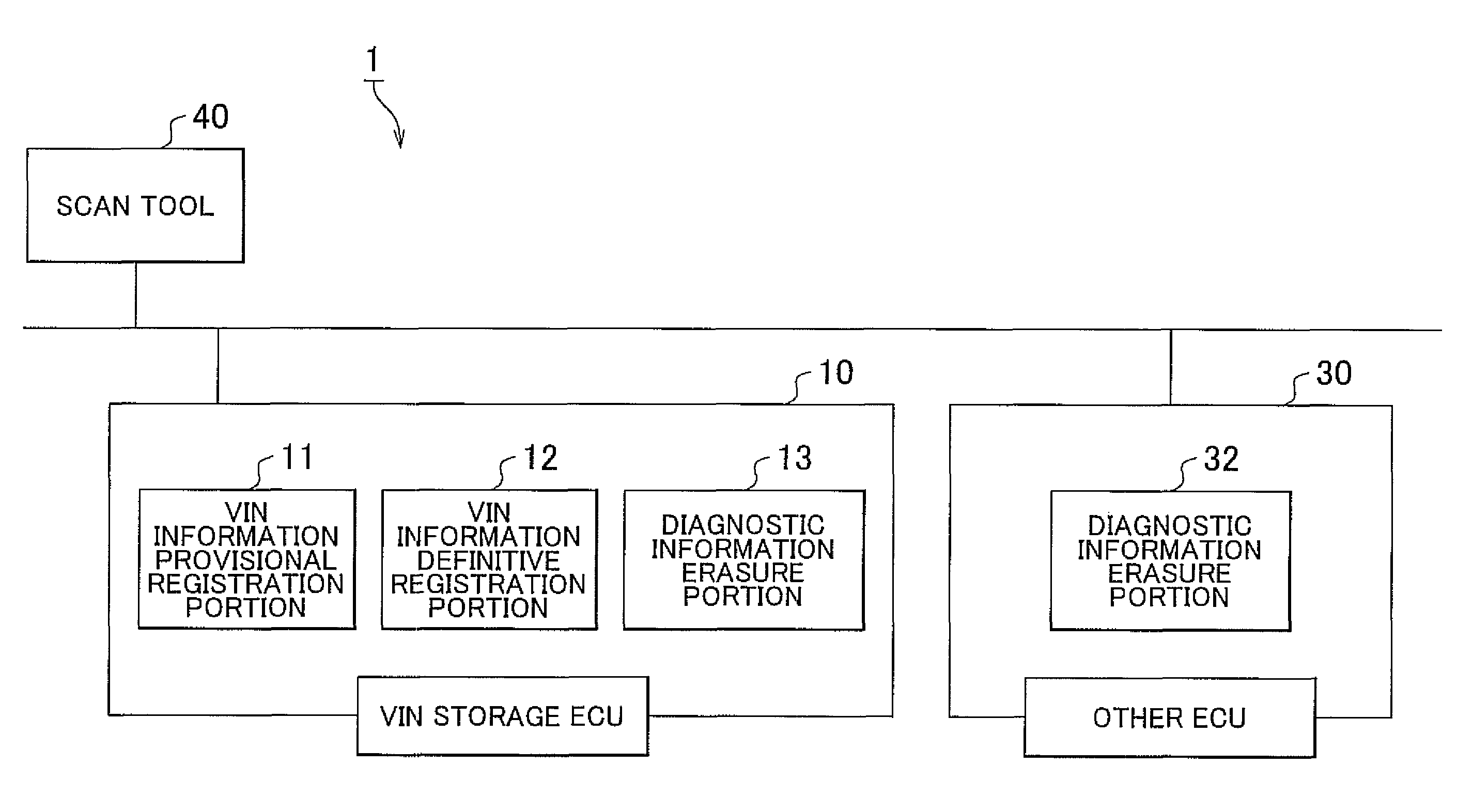
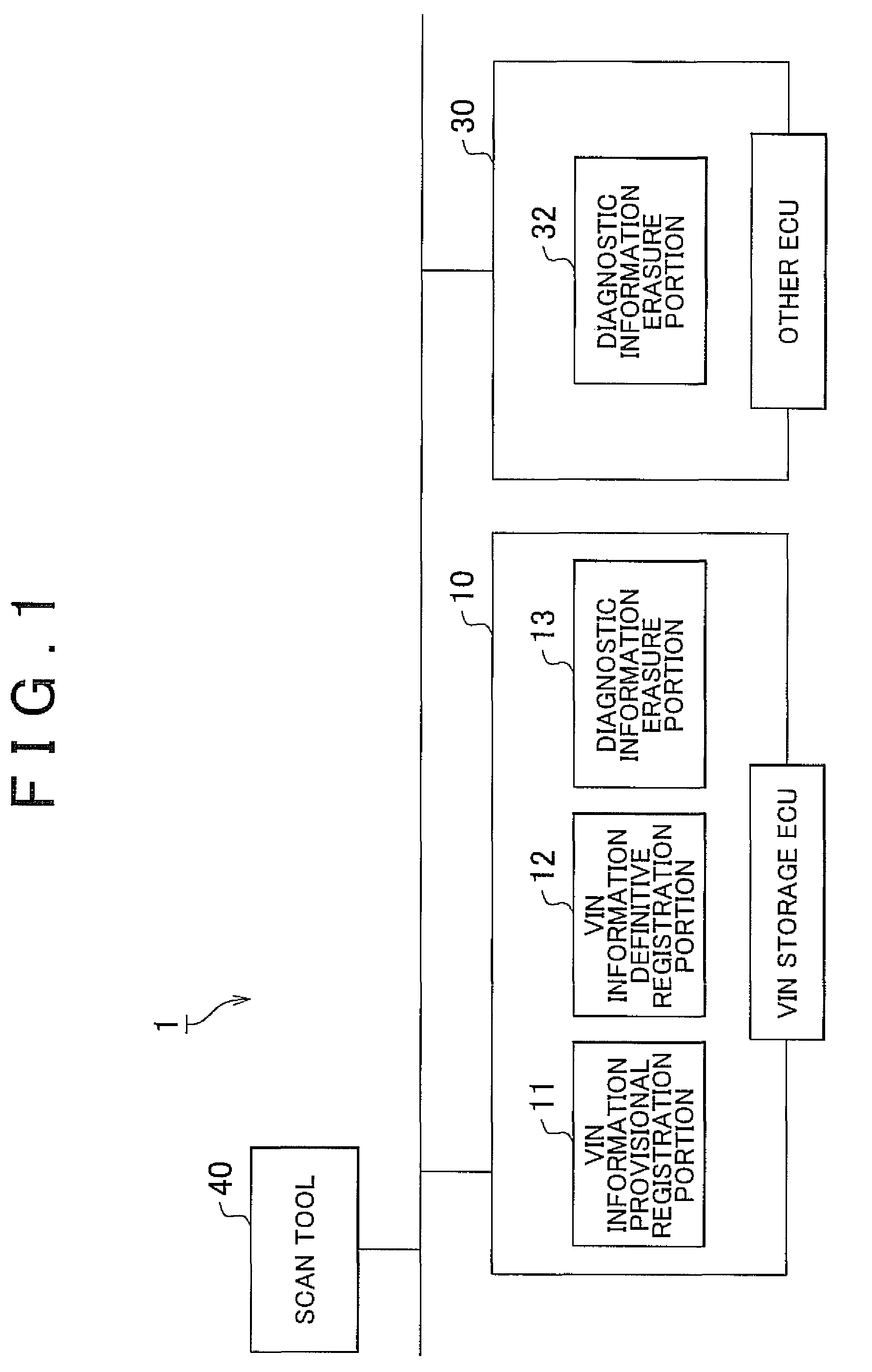
FIG. 1 is a system construction diagram showing a construction of portions of a failure diagnosis system 1 according to the invention.
The failure diagnosis system 1 includes an ECU that has a vehicle identification number (VIN) (hereinafter, referred to as “VIN storage ECU”) 10, other ECUs that do not have the VIN (hereinafter, regarded as a single ECU and referred to as “other ECU”) 30, and a scan tool 40 capable of communicating with the VIN storage ECU 10 and the other ECU 30. A hardware construction of each of the VIN storage ECU 10 and the other ECU 30 is made up of a microcomputer, and is made up of a CPU, a ROM, a RAM, etc. that are interconnected by a bus (not shown).
The VIN storage ECU 10 is an ECU that stores the VIN, and that also carries out an on-board diagnosis (OBD) and stores diagnostic information. The diagnostic information is information related to emissions from the vehicle. In order to prevent atmospheric pollution, the VIN storage ECU 10 stores a result of fail...
second embodiment
The second embodiment, a scan tool 40 is constructed so as to send, together with a VIN write request, the VIN to be written, to a VIN storage ECU 10, in response to a specific input operation from a service person (an input operation for writing the VIN). In the following description, it is assumed that the VIN write request includes information that represents the VIN to be written.
The VIN storage ECU 10, as shown in FIG. 6, includes a diagnostic information erasure portion 13, a VIN information update portion 14, and an erasure command notification portion 15, as main functional portions that are related to the CARB OBD2 regulations.
The diagnostic information erasure portion 13 erases the diagnostic information from the VIN storage ECU 10 in response to the VIN write request from the scan tool 40. Thus, the diagnostic information of the VIN storage ECU 10 is reset to an initial value (e.g., the “UNKNOWN”).
The VIN information update portion 14 carries out the VIN writing pursuantl...
third embodiment
The third embodiment, a scan tool 40 is constructed so as to send (broadcast) a composite signal made up of a VIN write request and a diagnostic information erasure request simultaneously to a VIN storage ECU 10 and an other ECU 30, in response to a specific input operation from a service person (an input operation for writing the VIN). In the following description, it is assumed that the VIN write request includes information that represents the VIN to be written. The composite signal made up of the VIN write request and the diagnostic information erasure request may be a signal that has a data structure in which each of the request information pieces is incorporated, or may also be provided in such a form that the VIN write request and the diagnostic information erasure request are continuously and separately sent by the time-division multiplex method.
The VIN storage ECU 10, as shown in FIG. 7, includes a diagnostic information erasure portion 13 and a VIN information update porti...
PUM
 Abstract
Description
Claims
Application Information
 - R&D
- Intellectual Property
- Life Sciences
- Materials
- Tech Scout
- Unparalleled Data Quality
- Higher Quality Content
- 60% Fewer Hallucinations
Browse by: Latest US Patents, China's latest patents, Technical Efficacy Thesaurus, Application Domain, Technology Topic, Popular Technical Reports.
© 2025 PatSnap. All rights reserved.Legal|Privacy policy|Modern Slavery Act Transparency Statement|Sitemap|About US| Contact US: help@patsnap.com


