
Timepiece with a calendar mechanism

a timepiece and calendar technology, applied in mechanical clocks, instruments, horology, etc., can solve the problems of difficult product photography, and achieve the effect of good product photography

Active Publication Date: 2011-01-04
SEIKO EPSON CORP
View PDF14 Cites 0 Cited by
  • Summary
  • Abstract
  • Description
  • Claims
  • Application Information

AI Technical Summary

Benefits of technology

A timepiece with a calendar mechanism according to the present invention does not produce a step in the date display area and thus enables good product photography.
A step between the digits can therefore be eliminated when this two-digit display marker is displayed through the tens digit display aperture and ones digit display aperture because both the tens digit and the ones digit are numerals disposed on the tens display wheel.
In addition, by displaying the tens digit and the ones digit in the two-digit display marker of the tens display wheel, the tens digit and the ones digit can be displayed at appropriate positions in the tens digit display aperture and ones digit display aperture with no deviation in the distance between the tens and ones digits or deviation in the vertical or horizontal alignment of the digits when seen from the face of the dial. Shadows are therefore not produced by a step between the digits when photographing the product, the problems and tedium of adjusting the lighting to eliminate such shadows are eliminated, and good pictures of the product can therefore be taken.
When the date is from the 1st to the 29th with this aspect of the invention, the numeral displayed in the ones digit display aperture changes day by day, and the numeral displayed in the tens digit display aperture changes every ten days. Compared with a configuration that has the numbers 1 to 31 on the date wheel and displays the date through a single calendar window, the invention can display the date using larger numerals by displaying the ones and tens digits separately, and the date can thus be read more easily.
In addition, when the date is the 30th or 31st, the “3” for the tens unit in the end-of-month markers is displayed from the tens digit display aperture, and the 0 or 1 for the ones unit displayed beside the tens unit is displayed from the ones digit display aperture. More specifically, when the date is the 30th or 31st, the date is displayed by the tens display wheel, and a step between the numeral displayed in the tens digit display aperture and the numeral displayed in the ones digit display aperture can be eliminated.
In this aspect of the invention the tens drive teeth disposed to the ones display wheel transfer drive power to the tens drive mechanism to drive the tens display wheel. It is therefore not necessary to provide separate drive motors for the ones display wheel and the tens display wheel, and drive power from a single source can be used to drive both the ones display wheel and the tens display wheel. The configuration is thus simplified, the limited space inside a small timepiece can be used effectively, and the size of the timepiece can be reduced.

Problems solved by technology

A problem with the timepiece taught in JP-A-2000-65957, however, is that because the height (elevation) of the ones display member and the height (elevation) of the tens display member are not the same, a step occurs between the numbers in all displayed dates.
Because this step between the digits can cast a shadow when the product (timepiece) is photographed, for example, care is required when determining the angle from which pictures are taken, thus making product photography more difficult.

Method used


Image

  • Timepiece with a calendar mechanism
  • Timepiece with a calendar mechanism
  • Timepiece with a calendar mechanism

Examples


Embodiment Construction

A preferred embodiment of a timepiece with a calendar function according to the present invention is described below with reference to the accompanying figures.

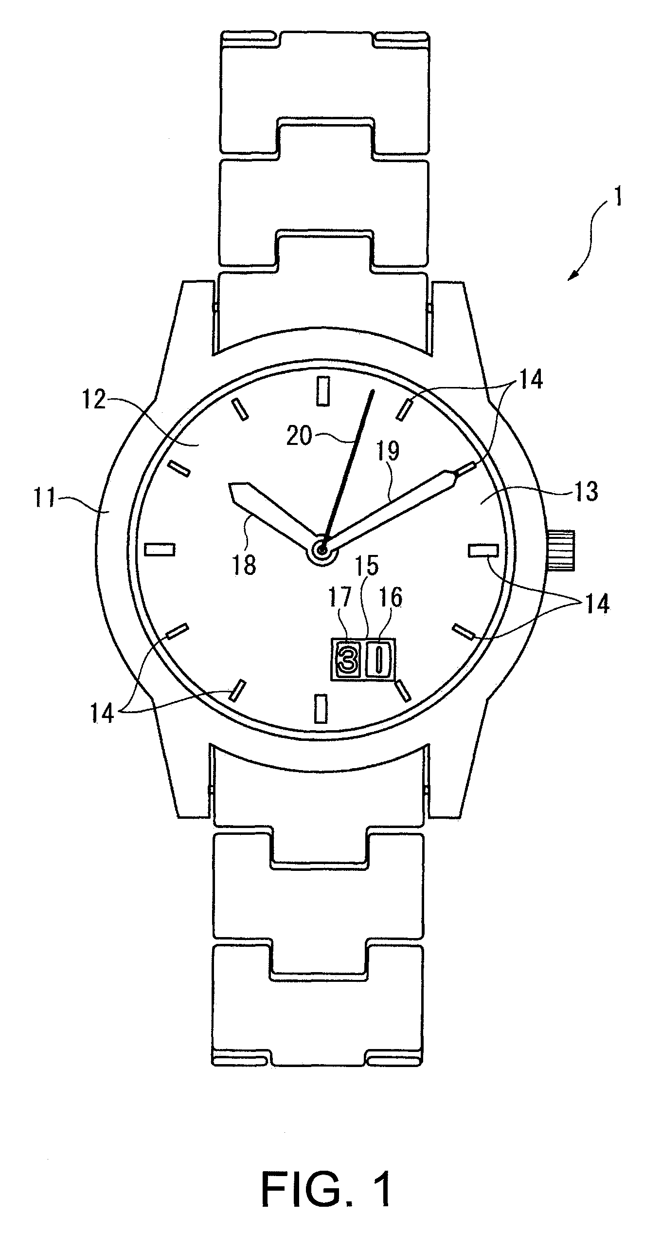
FIG. 1 is a schematic plan view of a timepiece with a calendar function according to a preferred embodiment of the invention.

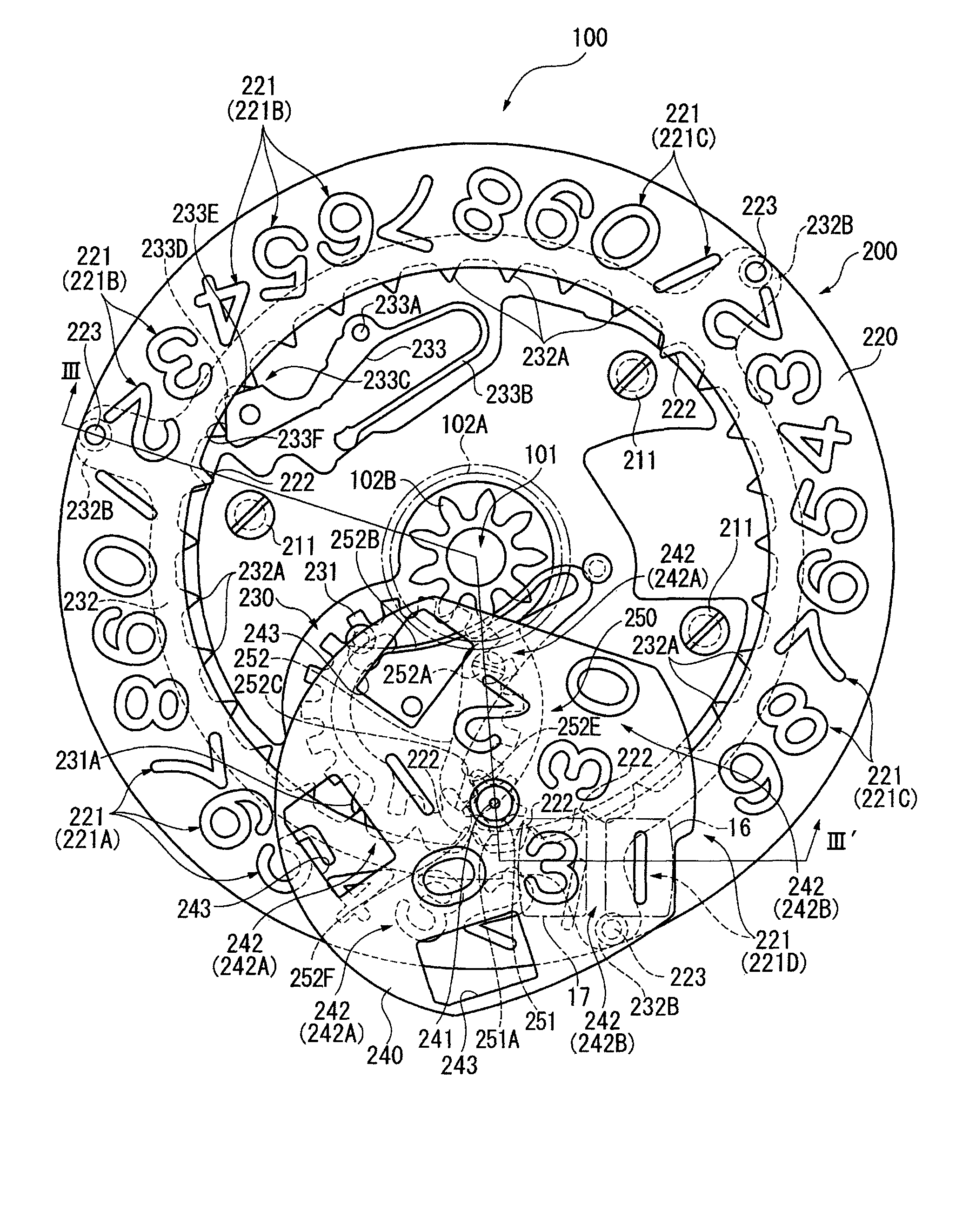
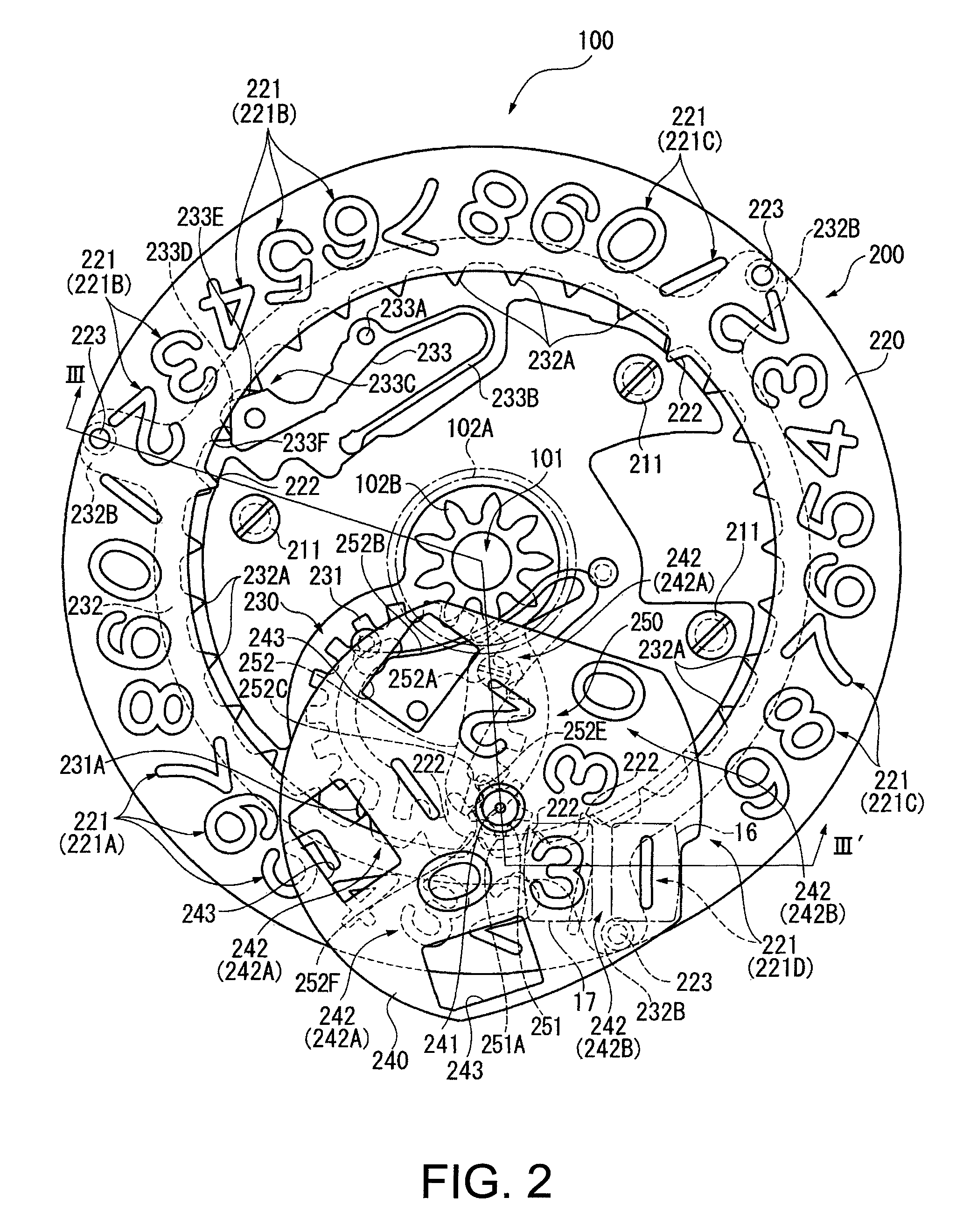
FIG. 2 is a plan view schematically showing the inside of a timepiece with a calendar function according to the invention when the dial is removed.

FIG. 3 is a section view through line III-III′ in FIG. 2.

FIG. 4 is a section view through the area near the date display window when a date from 1 to 29 is displayed.

* Configuration of a Timepiece with a Calendar Function

In FIG. 1 reference numeral 1 denotes a timepiece with a calendar function, and this timepiece with a calendar function 1 (referred to below as timepiece 1) has a case 11 with a crystal 12, a dial 13 that can be seen through the crystal 12, and a movement 100 (see FIG. 2) that is contained inside the case 11.

The dial 13 is round and has marke...


PUM


Abstract

A timepiece with calendar function including a dial having a tens digit display aperture for displaying the tens digit of the date and a ones digit display aperture for displaying the ones digit of the date, and a calendar mechanism that displays the date by presenting specific numerals through the dial. The calendar mechanism includes a ones display wheel having ones markers whereby the ones digit is displayed through the ones digit display aperture, a tens display wheel having tens markers whereby the tens digit is displayed through the tens digit display aperture, a ones drive mechanism that drives the ones display wheel, and a tens drive mechanism that drives the tens display wheel. The tens markers include normal tens markers that display only the tens digit in the tens digit display aperture, and a two-digit display marker that displays a tens digit in the tens digit display aperture and a ones digit in the ones digit display aperture.

Description

BACKGROUND1. Field of InventionThe present invention relates to a timepiece with a calendar mechanism that has a date display mechanism for displaying the date.2. Description of Related ArtSmall timepieces such as wristwatches and other timepieces with a calendar mechanism for displaying the date in the dial are known from the literature. When the calendar mechanism causes a date wheel displaying the numbers 1 to 31 near the periphery of the timepiece to rotate one revolution per month, the numbers used to display the date in such timepieces become quite small. As a result, configurations that display the ones and tens digits separately are also known from the literature (see, for example, Japanese Unexamined Patent Appl. Pub. JP-A-2000-65957.The timepiece taught in JP-A-2000-65957 is a device that displays the dates 1 to 31 using a ones display member that advances one step per day and bears the numbers 0 to 9, and a tens display member that advances one step every ten days and bea...

Claims


Application Information

Patent Timeline
Patent Type & Authority Patents(United States)
IPC IPC(8): G04B19/20
CPCG04B19/247
Inventor HIRAYA, EIICHI
Owner SEIKO EPSON CORP
Learn More