
System and method for mixing distinct air streams

a technology of distinct air streams and mixing methods, applied in the direction of drying machines with progressive movements, lighting and heating apparatus, furnaces, etc., can solve the problems of inability to uniformly profile the heated air in the system, the necessary mixing of the air with the combustion products is potentially hazardous to the end product, and the profile can irreversibly damage the finished product, etc., to achieve the effect of increasing the drying efficiency of the drying system, increasing the mixing and heating efficiency, and reducing the siz

Active Publication Date: 2011-01-04
VALMET OY
View PDF28 Cites 6 Cited by
  • Summary
  • Abstract
  • Description
  • Claims
  • Application Information

AI Technical Summary

Benefits of technology

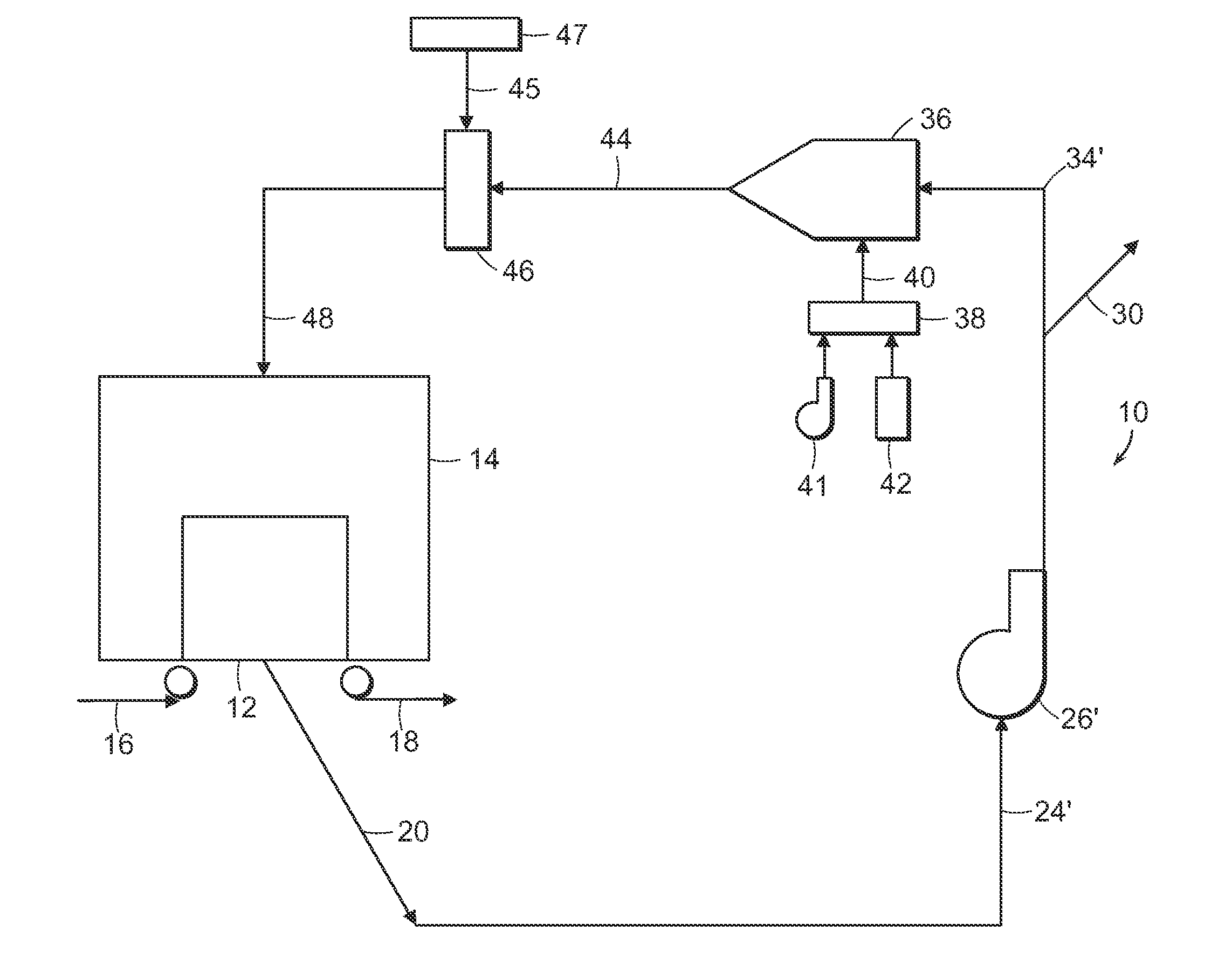
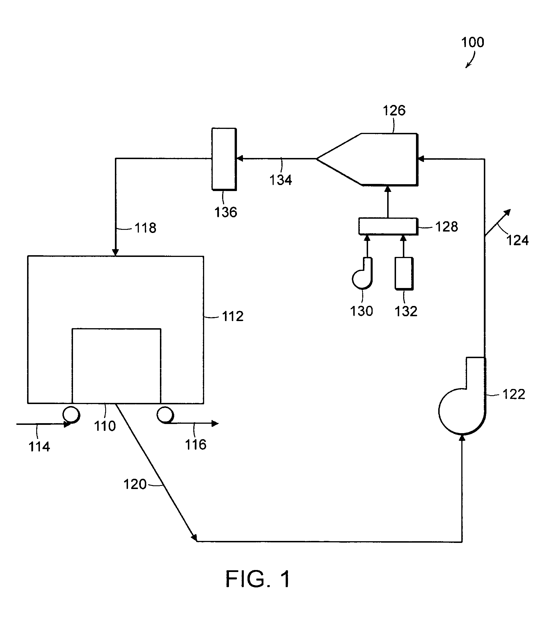
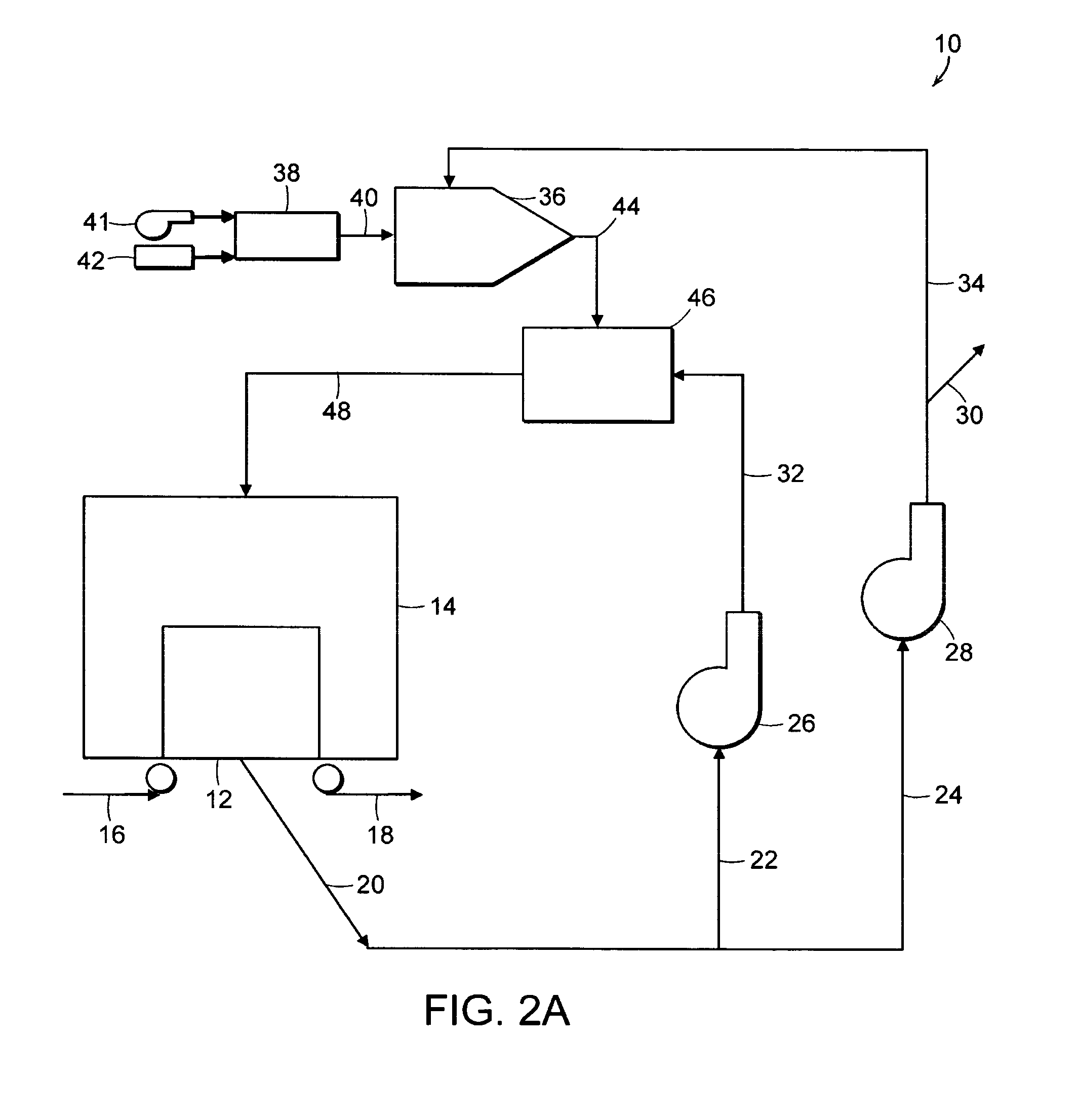
[0012]Accordingly, the present invention relates to a novel drying system that incorporates two-stage processes for heating air for drying a traveling web. In its various embodiments, the present invention operates within a system having a drying hood containing a dryer. The drying hood receives heated air through an intake and expels system air through an exhaust, a portion of which is directed into the atmosphere. In one embodiment, the portion of system air that is maintained in the system is divided into two portions and directed into separate parallel loops for two-stage heating that results in greater temperature uniformity and efficiency within the drying system.
[0015]By dividing the heating process into two stages, the present invention greatly increases the drying efficiency of a drying system. Notably, although one embodiment of the present invention utilizes a pair of distinct conduits for the heating process, the physical size of the drying system will not be affected. On the contrary, because of the increased mixing and heating efficiency of the present invention, it is possible to construct a drying system that is both smaller in size and more energy efficient that those presently used in the industry. Moreover, as described further below, the two-stage process of the present invention can also be utilized in a single conduit dryer configuration, in which the injection chamber is used for injecting an external source of heated air into the stream of mixed air from the mixing chamber. Numerous sources of external heated air, described below, can be utilized for improving the performance and efficiency of industrial dryers.

Problems solved by technology

Those skilled in the art will recognize that the combination of the system air and the combustion products will not necessarily produce a uniformly profiled stream of heated air.
While the current art is able to make remarkable use of system air through the re-circulation mechanisms, the necessary mixing of that air with combustion products is potentially hazardous to the end product.
Particularly for the manufacture of lightweight materials, such as tissue paper, any deviation in the temperature profile can irreversibly damage the finished product.
The economic effects of non-uniform heating are multiple, including the energy required to replace the lost product, the costs of replacing the wasted raw materials, and the labor necessary to fix, maintain, manage and operate the dryer through a new production cycle.
In particular, the baffle design does create a large eddy that induces mixing of the fluid streams, but it does not do so in a symmetrical or uniform manner.
Each of these two solutions involves non-trivial modifications to the drying systems described above, and both solutions would cost the producer in terms of energy efficiency and space utilization.

Method used


Image

  • System and method for mixing distinct air streams
  • System and method for mixing distinct air streams
  • System and method for mixing distinct air streams

Examples


Embodiment Construction

[0032]The present invention includes both a system and method for mixing fluid streams, particularly those associated with contemporary drying systems. As described below, the present invention solves a number of problems noted in the textiles, paper and non-wovens industries. Most notably, the present invention includes a significant redesign of the drying system that efficiently utilizes system air and mixes it with combustion products in order to produce uniformly heated air for the web of goods. The mixing efficiencies of the present invention allow for a compact dryer design that is more economical in terms of raw materials, energy and space utilization.

[0033]Turning to FIG. 2A, the system 10 for drying a textile web is shown. As shown, the system 10 is represented schematically, thus it should be understood that the novel features of the present invention are equally applicable to all types of industrial mixers, including at least TAD's, floatation dryers and Yankee impingemen...


PUM


Abstract

The present invention relates to novel dryer systems that incorporate two-stage processes for heating air for drying a traveling web. The present invention is operable within a drying system having a drying hood containing a dryer. The drying hood receives heated air through an intake and expels system air through an exhaust. The portion of system air that is maintained in the system is divided into two portions and directed into separate parallel conduits for two-stage heating that results in greater temperature uniformity and efficiency within the system. One loop includes a mixing chamber for the initial mixing of system air with the combustion products of a burner. A second loop includes an injection chamber that receives the initially mixed air and injects it into the other portion of the system air, resulting in greater temperature uniformity within the drying hood and increased operating efficiency for the entire system.

Description

BACKGROUND OF THE INVENTION[0001]1. Field of the Invention[0002]The present invention relates generally to the field of fluid dynamics and heat transfer, and more specifically to a system and method for mixing fluid streams within an industrial drying machine.[0003]2. Description of the Prior Art[0004]Industrial machines, such as those common in the textile, nonwovens and paper manufacturing industries, commonly utilize heated air to dry a newly formed product, as well for thermal bonding, curing and other processes that require an air stream with a uniform temperature profile. Typically, air is heated through conventional combustion means and then directed in various fashions towards the web of wet material. The heated air passes through or impinges the web, losing some of its heat in the drying process. The cooled air, referred to as system air, is then divided into portions that are re-circulated through the drying machine and portions that are exhausted into the atmosphere.[0005...

Claims


Application Information

Patent Timeline
Patent Type & Authority Patents(United States)
IPC IPC(8): F26B5/04F26B3/00
CPCF26B13/10F26B23/02F26B21/04
Inventor SOLOMON-GUNN, MARGARET E.PARENT, LAURENT R.COTTA, LYNN C.
Owner VALMET OY
Learn More