
Humidification system for fuel cell

a fuel cell and humidification system technology, applied in the field of humidification system for fuel cells, can solve the problems of reduced humidification efficiency, difficult to meet the needs of use, and difficulty in increasing humidification, so as to achieve the same level of humidification performance and high humidification performance. , the effect of relatively low cos

Active Publication Date: 2010-12-28
HYUNDAI MOTOR CO LTD +1
View PDF8 Cites 6 Cited by
  • Summary
  • Abstract
  • Description
  • Claims
  • Application Information

AI Technical Summary

Benefits of technology

This configuration enhances humidification performance, reduces pressure drop and blower load, and minimizes flooding, while using less expensive materials, thereby improving the overall efficiency and durability of the fuel cell system.

Problems solved by technology

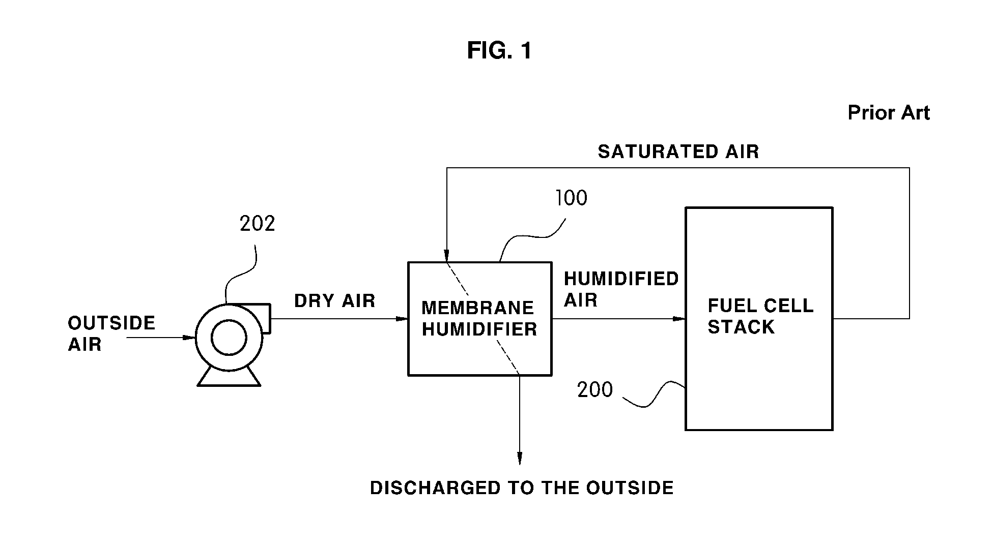
Moreover, since the wet air is diffused very slowly, the difficulty becomes more considerable.
As a result, the rate that the wet air penetrates into the inside of the hollow fiber membrane module 107 is very low, and thus the humidification efficiency is reduced.
Such a problem becomes more serious when the amount of dry air is increased, i.e., when the fuel cell stack provides a high output voltage.
Another problem of the conventional humidification system is caused by the hollow fiber membranes and the arrangement thereof.
Despite the advantage that the membrane humidifier is applicable for use with a vehicle, available hollow fiber membrane materials are very expensive, and thus it disadvantageous especially in terms of the manufacturing cost.
In the case of membrane humidifiers, a Nafion membrane is widely used as the hollow fiber membrane material applied to the fuel cell stack, more particularly, to a membrane electrode assembly (MEA), and thus it is disadvantageous in terms of cost reduction.
Since a large amount of water is produced and a high humidity is provided in the high current region of the fuel cell system, an increase in resistance of cathode material transfer and a flooding phenomenon may occur, which results in air starvation of the cathode.
As a result, the deterioration of the fuel cell catalyst is accelerated and thus the durability of the fuel cell is reduced.
Similarly, in the case where only Nafion is used as the material for the hollow fiber membranes, there are numerous problems to be overcome.

Method used


Image

  • Humidification system for fuel cell
  • Humidification system for fuel cell
  • Humidification system for fuel cell

Examples


Embodiment Construction

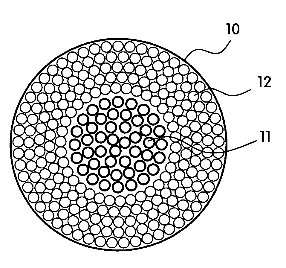
[0049]As described herein, the present invention includes a humidification system for a fuel cell, where the humidification system comprises a hollow fiber membrane module and a hollow fiber membrane bundle disposed therein. In certain preferred embodiments, the humidification system further comprises a plurality of hollow fiber membranes that is swollen with water arranged in the center of the hollow fiber membrane bundle through which dry air supplied from the outside by a blower flows. In other preferred embodiments, the humidification system comprises a plurality of hollow fiber membranes that is not swollen with water disposed on the outside of the hollow fiber membrane bundle through which wet air discharged from a fuel cell stack mainly flows.

[0050]The invention can also include a motor vehicle comprising a fuel cell according to any of the embodiments as described herein.

[0051]Reference will now be made in detail to the preferred embodiments of the present invention, example...


PUM

PropertyMeasurementUnit
RHaaaaaaaaaa
packing densityaaaaaaaaaa
power consumptionaaaaaaaaaa

Abstract

The present invention provides a humidification system with membranes of different species, in which a material having a high humidification performance and capable of being swollen with water is arranged in the center of a hollow fiber membrane bundle disposed in a hollow fiber membrane module and a material that is not swollen with water is disposed on the outside thereof. Accordingly, using the humidification system of the invention, it is possible to provide the same level of humidification performance as the existing humidification system, manufacture the humidification system at low cost, and solve various problems such as a flooding phenomenon of a fuel cell stack and an increase in load on an air blower.

Description

CROSS-REFERENCE TO RELATED APPLICATION[0001]This application claims under 35 U.S.C. §119(a) the benefit of Korean Patent Application No. 10-2008-0020787 filed Mar. 6, 2008, the entire contents of which are incorporated herein by reference.BACKGROUND[0002](a) Technical Field[0003]The present invention relates to a humidification system for a fuel cell. More particularly, the present invention relates to a humidification system with membranes of different species, in which a material having a high humidification performance and capable of being swollen with water is arranged in the center of a hollow fiber membrane bundle disposed in a hollow fiber membrane module and a material that is not swollen with water is disposed on the outside thereof.[0004](b) Background Art[0005]It can be necessary to humidify an electrolyte membrane in a fuel cell for the operation of the fuel cell, and thus a humidification system, in which water of exhaust gas, i.e., wet gas, discharged from the fuel cel...

Claims


Application Information

Patent Timeline
Patent Type & Authority Patents(United States)
IPC IPC(8): H01M8/04
CPCB01D63/02H01M8/04141H01M8/04149F24F2003/1435H01M2008/1095H01M2250/20Y02E60/50Y02T90/32B01D2313/08B01D2319/06Y02P70/50Y02T90/40H01M8/04
Inventor KIM, HYUN YOO
Owner HYUNDAI MOTOR CO LTD
Learn More