Electromagnetic actuator

a technology of electromagnetic actuators and actuators, which is applied in the direction of magnets, magnetic bodies, instruments, etc., can solve the problems of reducing the miniaturization and weight of electromagnetic actuators, reducing the number of elements, and complicated determining the rotation range of the output shaft, so as to reduce the number of elements and reduce the weight

Inactive Publication Date: 2010-12-28
RICOH IMAGING COMPANY
View PDF12 Cites 3 Cited by
  • Summary
  • Abstract
  • Description
  • Claims
  • Application Information

AI Technical Summary

Benefits of technology

[0007]The present invention provides an electromagnetic actuator in which miniaturization and weight reduction are achieved by a reduction in the number of elements to make the electromagnetic actuator applicable to a small apparatus such as a camera. The present invention further provides an electromagnetic actuator in which the range of rotation of the output shaft can be freely determined and which can be easily produced.
[0009]The electromagnetic actuator according to the present invention can limit the range of rotation of the movable member and hold the rotation position of the movable member by making the rotating portion of the movable member come into contact directly with the stopper of the stationary member that is made of a permanent magnet while magnetically attracting and holding the rotating portion of the movable member by the magnetic force of the permanent magnet. Therefore, as compared with an electromagnetic actuator such as disclosed in Patent Publication 1 that includes a plurality of permanent magnets and a rotary plate stopper which are provided independently of each other, a further reduction in the number of elements, further miniaturization and a further weight reduction become possible in the electromagnetic actuator according to the present invention. Additionally, since the angular position of rotation and the range of rotation of the movable member can be determined simply by designing the stationary member, the range of rotation of the movable member can be easily determined; moreover, the electromagnetic actuator can be easily produced.
[0011]The sector-shaped core that is provided at one end of the shaft portion is magnetized into one of an S-pole and an N-pole while the other end of the shaft portion or the sector-shaped core joined to this other end of the shaft portion is magnetized into the other polarity, so that a repulsive force and an attractive force in a circumferential direction are produced relative to the permanent magnet, which causes the sector-shaped core to rotate reciprocatively about the shaft portion. This makes it possible for the stationary member to be made of a single permanent magnet, thus making miniaturization and weight reduction of the electromagnetic actuator possible.
[0012]Specifically, it is desirable for two of the rotating portions to be joined to both ends of the shaft portion, respectively, and to be magnetized as opposite polarities, respectively, when the power supply supplies the current to the coil, wherein two of stationary members are positioned to correspond to the two sector-shaped portions, and radial-edge faces of each of the two stationary members are magnetized as one and the other of an S-pole and an N-pole. A repulsive force and an attractive force that are reciprocal with each other at each end of the shaft portion are produced to thereby obtain high torque. In addition, even in this configuration, the stationary member can be made of two permanent magnets in total, thus making miniaturization and weight reduction of the electromagnetic actuator possible.
[0019]Hence, it is possible to provide a small and light-weight camera can be made, and in addition, provide a high-speed mirror up / down operation and a high-speed shutter opening / shutting operation.

Problems solved by technology

Therefore, the plurality of permanent magnets and the rotary plate stopper need to be installed around the rotary plate, and also the number of elements of the electromagnetic actuator is large, which becomes an obstacle to miniaturization and weight reduction of the electromagnetic actuator.
Consequently, the design for determining the range of rotation of the output shaft becomes complicated, and it becomes difficult to set a desired rotational range for the output shaft.

Method used


Image

  • Electromagnetic actuator
  • Electromagnetic actuator
  • Electromagnetic actuator

Examples


embodiment 1

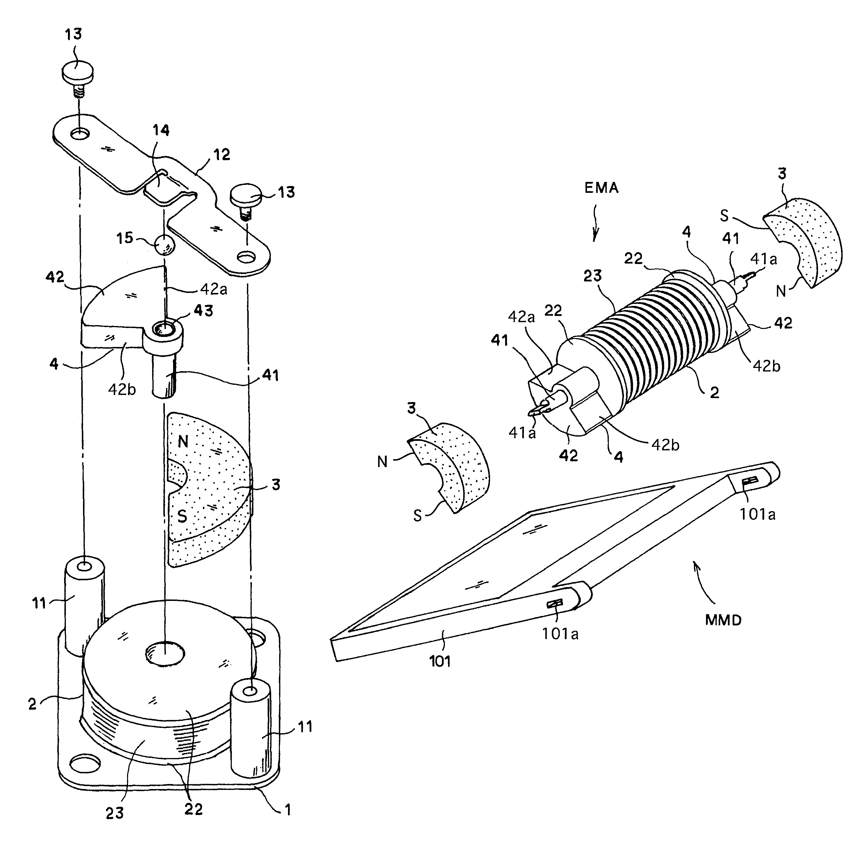
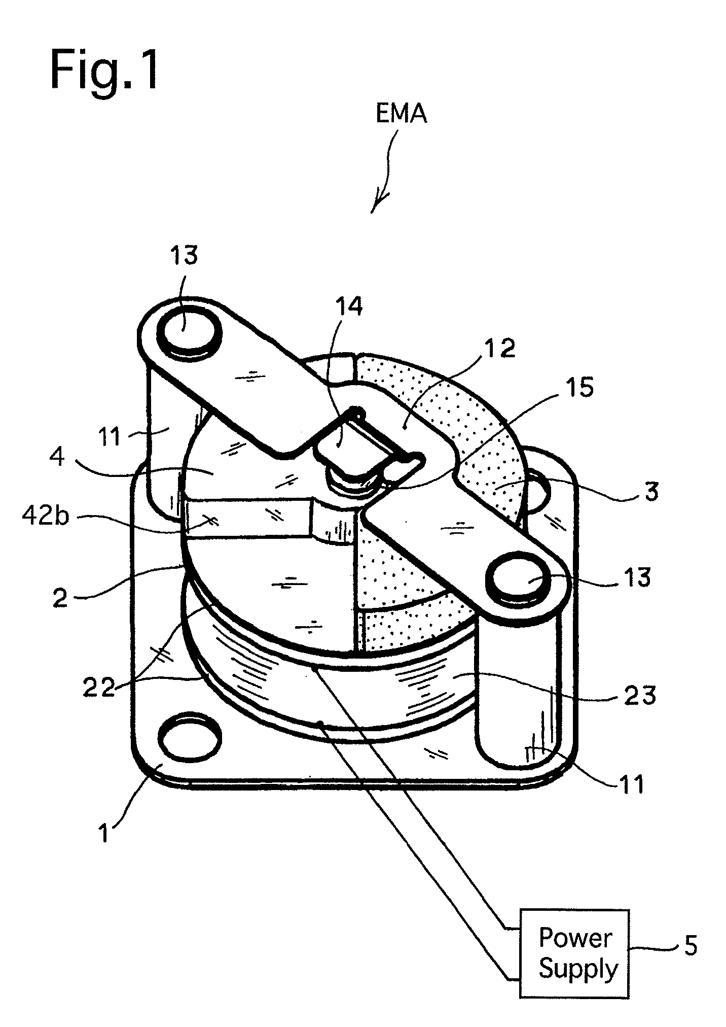
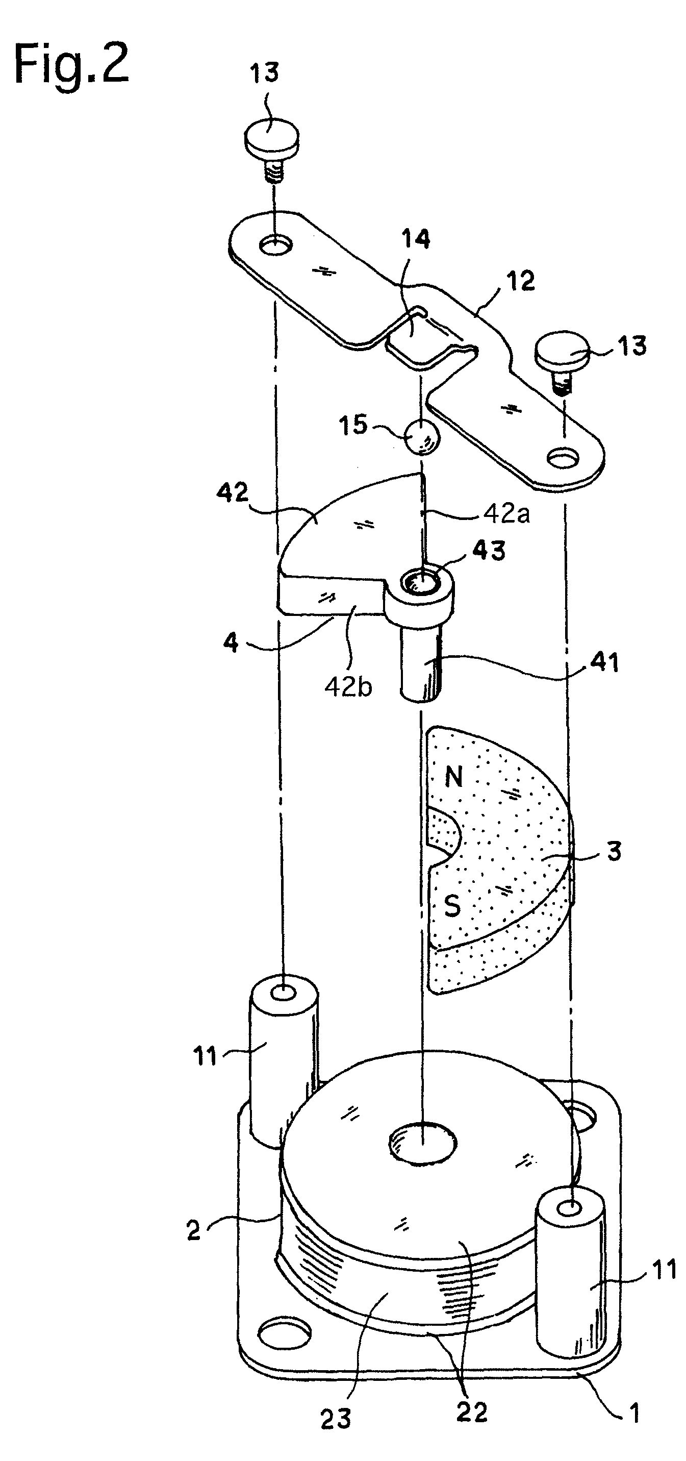
[0037]FIG. 1 is an external perspective view of an electromagnetic actuator EMA of Embodiment 1, showing the outward appearance thereof, and FIG. 2 is a perspective view of a portion of the electromagnetic actuator EMA. FIG. 3A is a plan view of a main part of the electromagnetic actuator EMA, and FIG. 3B is a cross sectional view taken along the A-A line shown in FIG. 3A. The electromagnetic actuator EMA is provided with a base (seating plate) 1, a cylindrical bobbin 2, a coil 23 and a permanent magnet 3. In these drawings, a cylindrical bobbin 2 made of a non-magnetic material, specifically an insulating material, is fixed onto the base (seating plate) 1 made of a substantially flat rectangular plate. The cylindrical bobbin 2 is provided at a center thereof with a hollow cylindrical portion 21, and is further provided, at the opposite ends of the hollow cylindrical portion 21 in the axial direction thereof, with two disk flanges 22, respectively. Clad wire is wound around the holl...

embodiment 2

[0045]FIG. 5 is a schematic diagram of an SLR camera CAM in Embodiment 2 that includes a mirror drive device MMD to which the electromagnetic actuator EMA according to the present invention is applied, showing the internal structure of the SLR camera CAM. The camera body 100 of the SLR camera CAM is structured so that a photographing lens 110 can be attached to the front of the camera body 100 and so that object light to be formed as an object image via the photographing lens 110 is reflected upward by a main mirror (quick-return mirror) 101 installed inside the camera body 100 to be formed as an object image onto a focusing screen 102 made of a transparent material such as glass or a plastics. The object image formed on the focusing plate 102 can be viewed by the user of the SLR camera CAM through a finder optical system 105 which includes an eyepiece lens 104, a pentagonal prism 103. At a time of exposure by a depression of a release button (not shown), the main mirror 101 is rota...

embodiment 3

[0053]FIGS. 8A, 8B and 8C show the shutter device SD of the SLR camera CAM in Embodiment 3 to which two electromagnetic actuators according to the present invention are applied, showing the structure of a vertically-traveling focal plane shutter. The shutter device SD is composed of focal-plane shutter blades 200 and a shutter blade drive mechanism 230. The focal-plane shutter blades 200 that are driven to open and shut a rectangular photographing aperture AP are positioned in front of the electronic imaging device PD of the SLR camera CAM as shown in FIG. 5 or in front of silver-salt film. The shutter blade drive mechanism 230 drives the focal-plane shutter blades 200. The focal-plane shutter blades 200 are provided with an upper set of shutter blades 210 and a lower set of shutter blades 220. The upper set of shutter blades 210 includes a first shutter blade 211, a second shutter blade 212 and a third shutter blade 213, and the lower set of shutter blades 220 includes a first shut...


PUM


Abstract

An electromagnetic actuator is provided, including a bobbin made of a non-magnetic material including a hollow cylindrical portion and disk flanges; a coil formed between the disk flanges; a power supply which supplies a current to the coil; a movable member pivoted on the hollow cylindrical portion; and a stationary member made of a permanent magnet and fixed to a disk flange. The movable member is a magnetic material and includes a shaft portion and a rotating portion. The rotating portion is fixed to the shaft portion, lies on the disk flange, and extends in a radial direction of the shaft portion. When the power supply supplies the current to the coil in a predetermined direction, the rotating portion is magnetized to a predetermined polarity and rotates. The stationary member includes a stopper for stopping rotation of the movable member at a predetermined rotational position.

Description

BACKGROUND OF THE INVENTION[0001]1. Field of the Invention[0002]The present invention relates to an electromagnetic actuator including an electromagnet and a permanent magnet, and more specifically relates to such a type of electromagnetic actuator in which a movable member is reciprocatively rotatable.[0003]2. Description of the Related Art[0004]In apparatuses such as cameras which are provided therein with various movable mechanisms, it is often the case that one or more electromagnetic actuators are used as driving sources for the movable mechanisms.[0005]An electromagnetic actuator consisting of an output shaft, a plurality of permanent magnets and a rotary plate stopper has been proposed as a type of electromagnetic actuator in which a movable member is rotated, reciprocatively, in Japanese patent publication No. 2565656 (hereinafter referred to as Patent Document 1), wherein the output shaft is inserted into a hollow portion of a coil and has a rotary plate at one end of the o...

Claims


Application Information

Patent Timeline
Patent Type & Authority Patents(United States)
IPC IPC(8): G03B19/12
CPCG03B19/12H02K26/00H02K33/16
Inventor TSUJIYAMA, JUNKI
Owner RICOH IMAGING COMPANY
Why Eureka
Try Eureka