
Method and system for coupling an alarm system to an external network

a technology of alarm system and external network, applied in the field of security systems, can solve the problems of central monitoring system, one-way communication link not allowing remote access of security system, and telecommunication line becomes a potential single point of failure,

Active Publication Date: 2010-12-21
ICN ACQUISITION LLC
View PDF26 Cites 230 Cited by
  • Summary
  • Abstract
  • Description
  • Claims
  • Application Information

AI Technical Summary

Benefits of technology

This solution provides cost-effective, redundant communication links, enabling remote control and monitoring of legacy security systems, avoiding single-point failures and reducing replacement costs.

Problems solved by technology

One drawback of such a security system is that the telecommunications line becomes a potential single point of failure for providing a security breach signal to the central monitoring service system.
Such links between a security system and a central monitoring service system are typically one-way, providing only data from the security system to the central monitoring system, which is another drawback.
Such a one-way communication link does not allow for remote access of the security system to monitor or control the system.
The drawbacks with regard to these prior art systems are that should a dwelling already have a security system such as that described above, the legacy security system would have to be deinstalled and then replaced by a security system providing redundant communication modes and / or two-way communication.
There is no capacity to add such functionality to an existing alarm system.
Such replacement of a legacy security system entails high costs, as the controller unit of the legacy security system must be replaced, and the sensors need to be rewired to a new controller unit.

Method used


Image

  • Method and system for coupling an alarm system to an external network
  • Method and system for coupling an alarm system to an external network
  • Method and system for coupling an alarm system to an external network

Examples


Embodiment Construction

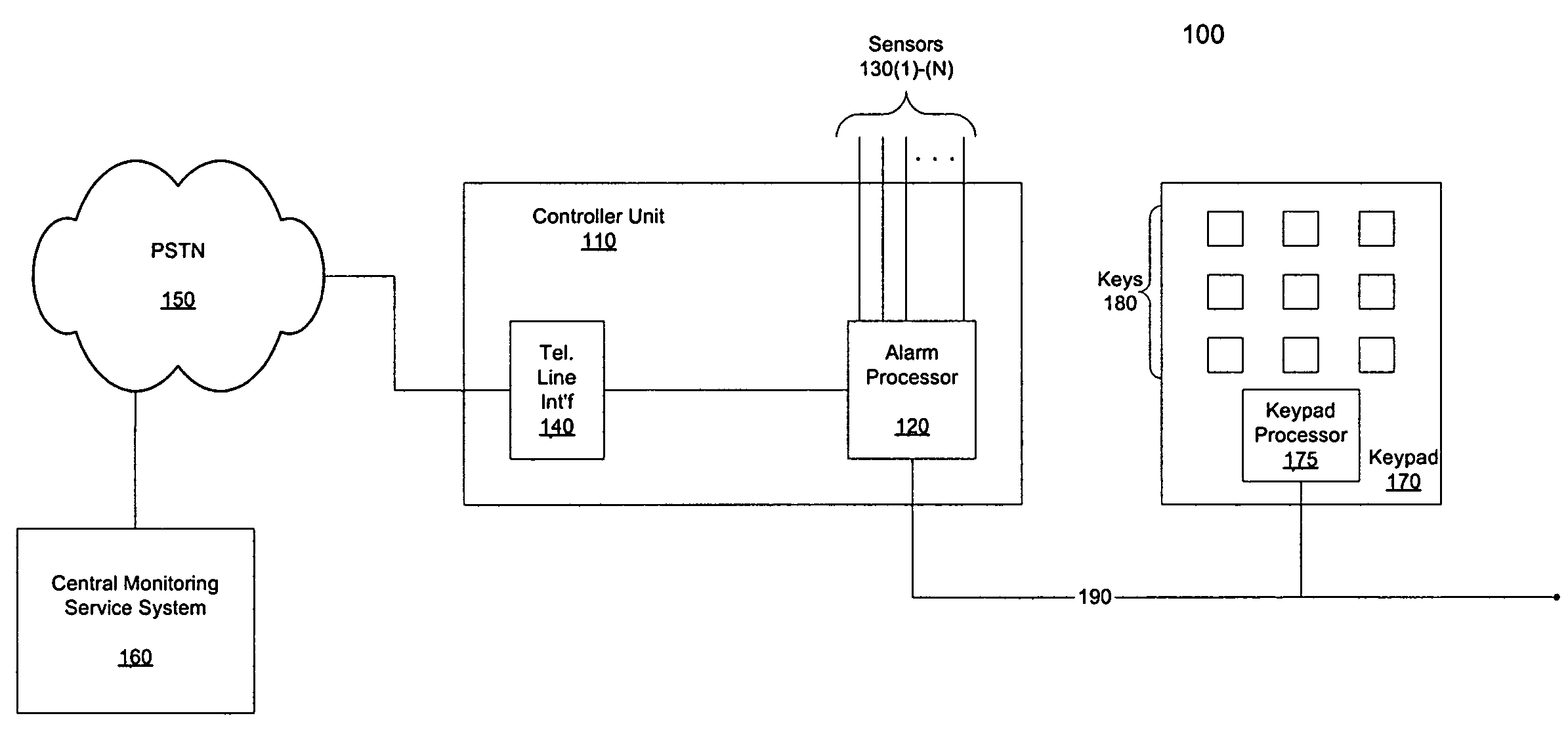
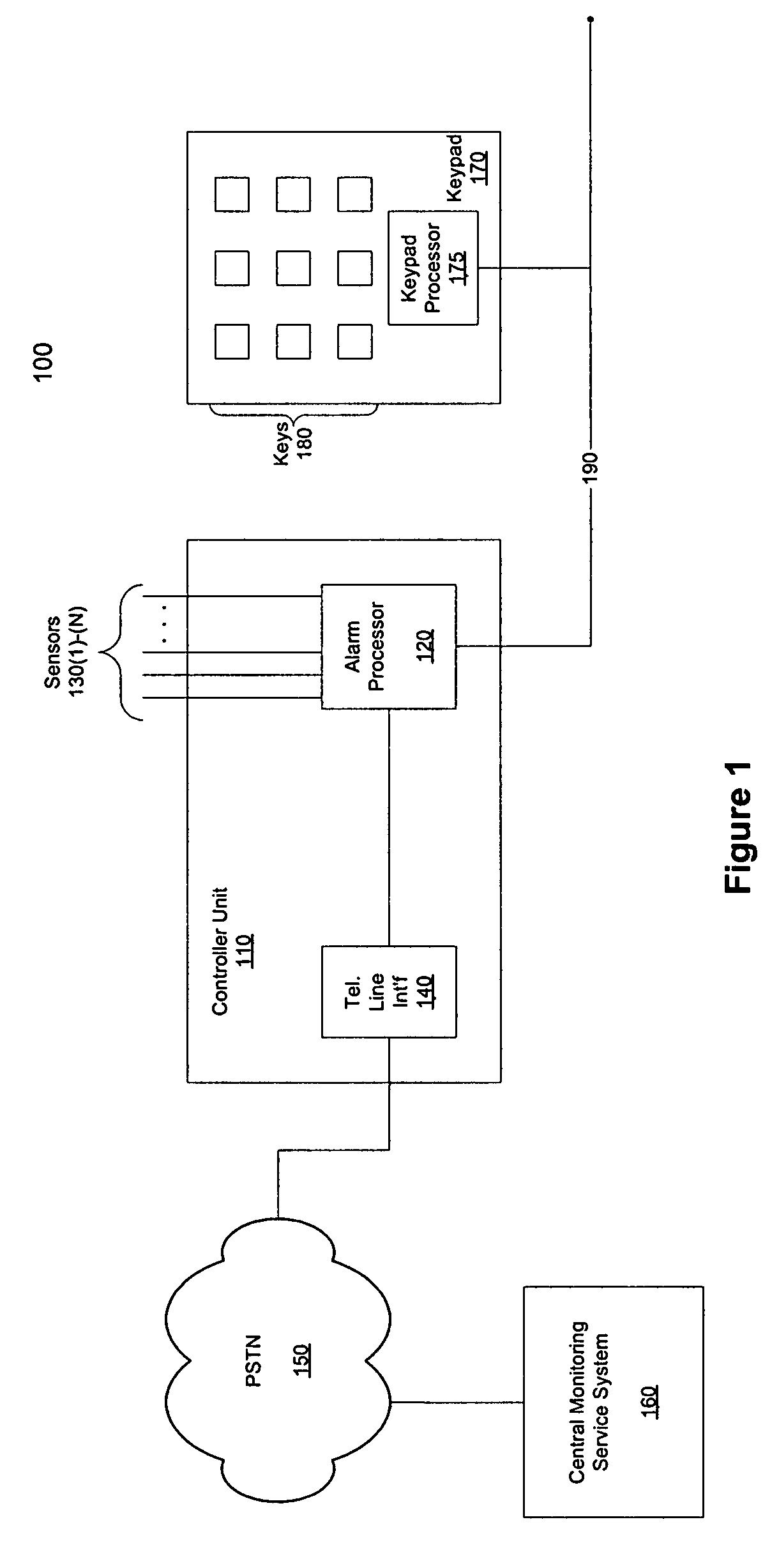
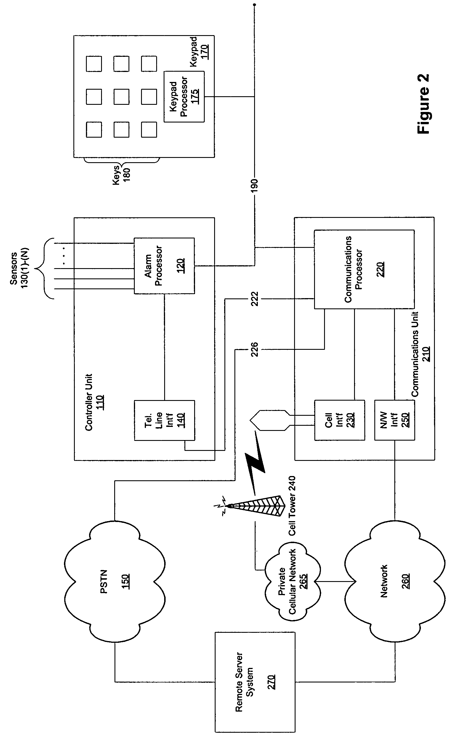
[0016]Embodiments of the present invention provide a communication system that can be added to a legacy alarm system to provide a plurality of communication modes to a remote server system from the legacy alarm system and provide remote control and monitoring to a user of the system via two-way communication links. Embodiments of the present invention can be configured to communicate with an alarm processor of the alarm system through use of a keypad bus typically used by the legacy alarm system for communications between the alarm processor and one or more keypads. Communication modes that can be provided by embodiments of the present invention can include, for example, communication over a public switched telephone network, cellular transmission, broadband transmission, and the like. Embodiments of the present invention can monitor all configured communication modes and determine which communication mode is the best for providing communication between the alarm system and the remo...


PUM


Abstract

A communication system is provided that can be added to a legacy alarm system to provide a plurality of communication modes to a remote server system from the legacy alarm system and provide remote control and monitoring to a user of the system via two-way communication links. The communication system can be configured to communicate with an alarm processor of the legacy alarm system through use of a keypad bus typically used by the legacy alarm system for communications between the alarm processor and one or more keypads. Communication modes that can be provided by embodiments of the present invention can include, for example, communication over a public switched telephone network, cellular transmission, broadband transmission, wireless broadband, and the like. The communication system can monitor all configured communication modes and determine which communication mode is the best for providing communication between the alarm system and the remote server. Through these communication modes and by virtue of being coupled to the alarm processor via the keypad bus, the communication system can provide both transmission to the remote server of the status and alarm condition of the legacy alarm system as well as provide control signals from the remote server to the legacy alarm system.

Description

CROSS REFERENCE TO RELATED APPLICATION[0001]This application claims priority to application Ser. No. 12 / 732,879 filed on Mar. 26, 2010, claiming the benefit of U.S. provisional application 61 / 174,366, filed on Apr. 30, 2009.FIELD OF THE INVENTION[0002]The present invention relates to the field of security systems, and more particularly relates to coupling a legacy alarm system to a server coupled to an external network via a plurality of monitored communication modes, enabling two-way communication between the server and the legacy alarm system.BACKGROUND OF THE INVENTION[0003]Security systems alert occupants of a dwelling and emergency authorities of a violation of premises secured by the security system. A typical security system includes a controller connected by wireless or wired connections to sensors deployed at various locations throughout the secured dwelling. In a home, sensors are usually deployed in doorways, windows, and other points of entry. Motion sensors can also be ...

Claims


Application Information

Patent Timeline
Patent Type & Authority Patents(United States)
IPC IPC(8): G08B29/00G09F25/00H04L12/28H03K17/94H03M11/00
CPCG08B25/08G08B25/14G08B29/16G08B25/004
Inventor COHN, ALAN WADEBATTLES, RONALD E.PROFT, DAVIDSHUMATE, SCOTT WILLIAM
Owner ICN ACQUISITION LLC
Learn More