Cooling of head actuator of disk device

a disk device and actuator technology, applied in the field of disk devices, can solve the problems of small airflow amount, inability to efficiently apply airflow to the end of the coil where the coil is heated, and small cooling effect of the coil, so as to achieve the effect of sacrificing the dust purge function

Inactive Publication Date: 2010-12-14
TOSHIBA STORAGE DEVICE CORP
View PDF6 Cites 4 Cited by
  • Summary
  • Abstract
  • Description
  • Claims
  • Application Information

AI Technical Summary

Benefits of technology

[0011]It is an object of the present invention to provide a disk device having an airflow dividing mechanism that guides air flowing along a wall surface of an enclosure out of an airflow generated by the rotation of a disk, to a coil part of a voice coil motor, and passes the airflow to a gap part between an upper magnet and a lower magnet of the voice coil motor, thereby avoiding sacrificing of dust purge performance, without interrupting an airflow other than the airflow which contributes to cooling of the coil.
[0013]According to the present invention, air that flows along the wall surface of the enclosure is guided to the coil part of the voice coil motor, out of the airflow generated by the rotation of the disk within the enclosure. The guided air is passed to a gap part between the upper magnet and the lower magnet of the voice coil motor to cool the coil. With this arrangement, the airflow other than the airflow which contributes to the cooling of the coil is not interrupted. Therefore, the coil of the voice coil motor can be cooled, without sacrificing the dust purge function.

Problems solved by technology

However, according to the configuration proposed by the data storage device and the hard disk drive described in JP-A-11-110960, the inflow amount of air is small, and the airflow cannot be efficiently applied to the end of the coil where the coil is heated most.
Therefore, this method has a problem in that the effect of cooling the coil is small.
However, according to this method, an airflow not contributing to the cooling is interrupted, and the amount of the airflow to a circulation filter provided in the downstream decreases.
As a result, dust purge performance decreases.

Method used


Image

  • Cooling of head actuator of disk device
  • Cooling of head actuator of disk device
  • Cooling of head actuator of disk device

Examples


Embodiment Construction

[0030]Before describing the preferred embodiments, an explanation will be given of the conventional disk drive shown in FIGS. 1A to 2.

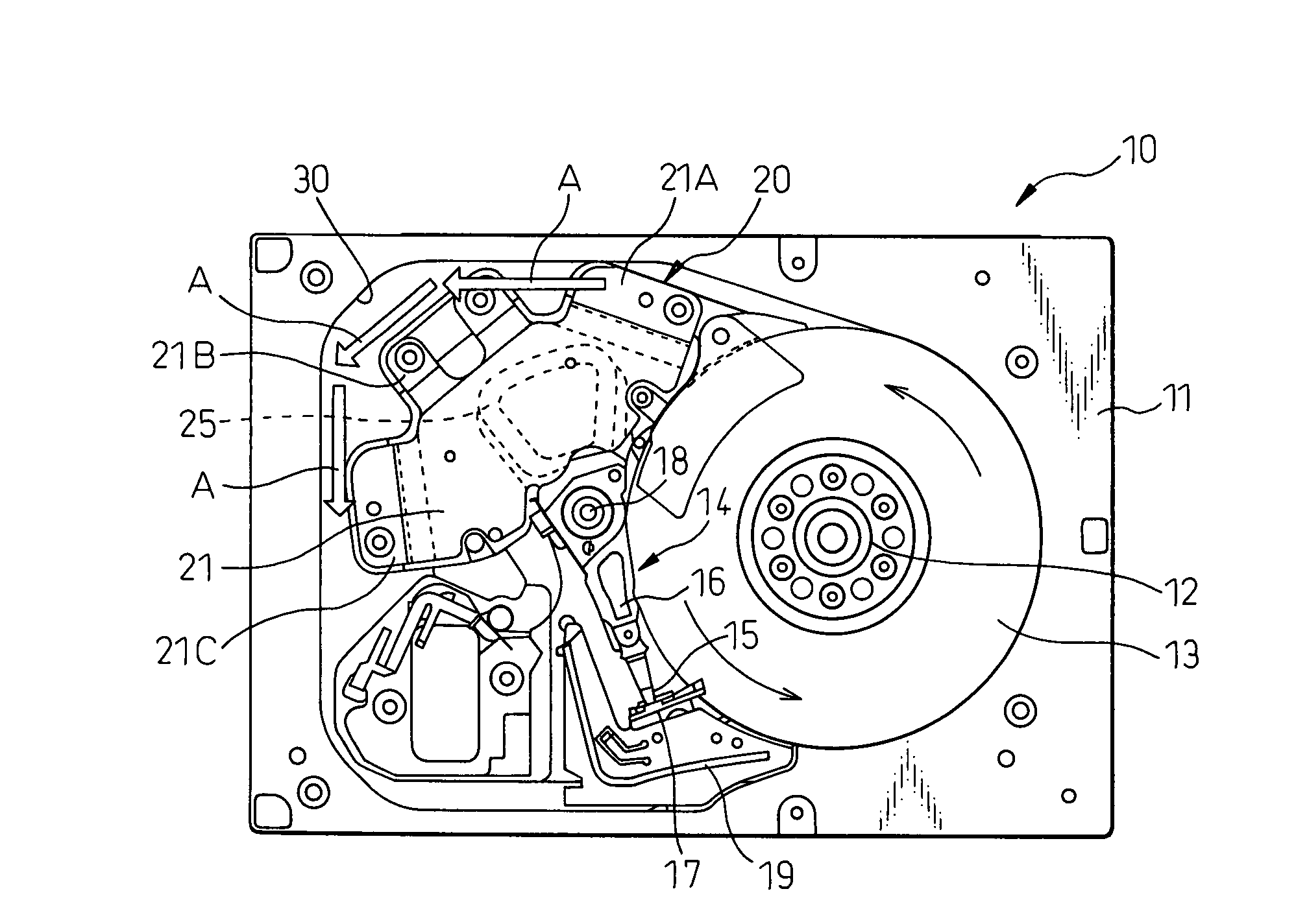
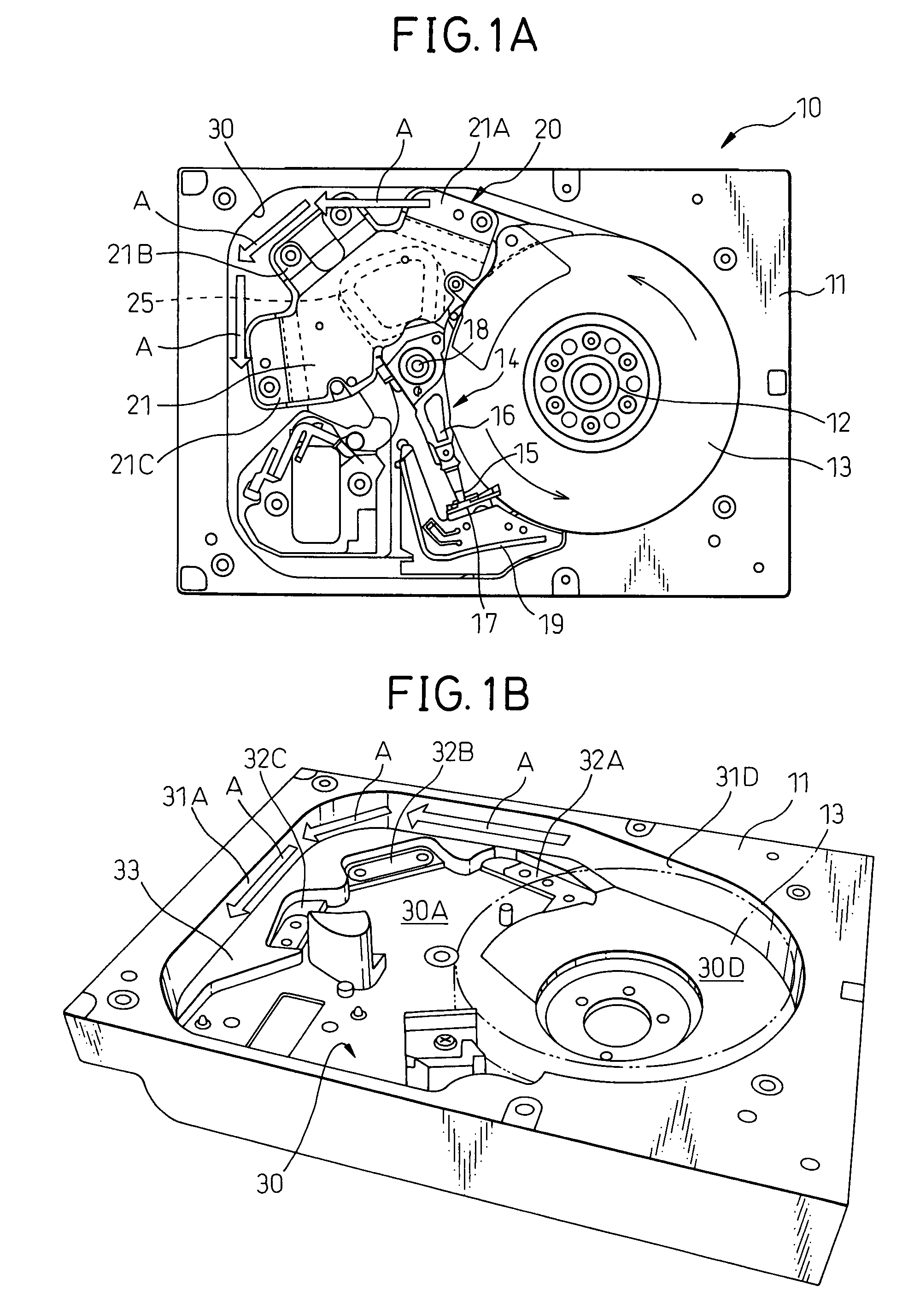
[0031]FIG. 1A and FIG. 2 show configurations of a conventional general magnetic disk device 10. The magnetic disk device 10 includes a spindle motor 12 in an inside 30 of an enclosure 11. At least one magnetic disk 13 is fitted to the spindle motor 12. The magnetic disk 13 stores data on it. A head actuator reads data recorded on the magnetic disk 13 or writes data onto the magnetic disk 13. The head actuator includes a rotation actuator assembly 14, and magnetic heads of head sliders 15 fitted to the front end of the rotation actuator assembly 14. A number of the head sliders 15 is equal to a number of the magnetic disks 13.

[0032]Each head slider 15 having a magnetic head is fitted to the front end of an arm member 16, and can move in a radial direction of the disk on the magnetic disk 13. When the magnetic disk device 10 is a load / unload system, the...


PUM

PropertyMeasurementUnit
temperatureaaaaaaaaaa
heightaaaaaaaaaa
lengthaaaaaaaaaa

Abstract

A magnetic disk device includes a swing-type head actuator which is driven by a voice coil motor. The voice coil motor is cooled by an airflow generated when a magnetic disk accommodated in a disk accommodating unit of an enclosure is rotated by a spindle motor. An airflow dividing member provided on an inner wall or a base of an actuator accommodating unit divides the airflow generated by the rotation of the disk and passing along the inner wall. The divided airflow is introduced to a coil part of the voice coil motor, and cools the coil, without sacrificing the dust purge performance.

Description

CROSS-REFERENCE TO RELATED APPLICATION[0001]This application claims priority from, and incorporates by reference the entire disclosure of, Japanese Patent Application No. 2006-296220, filed on Oct. 31, 2006.BACKGROUND OF THE INVENTION[0002]1. Field of the Invention[0003]The present invention relates to a disk device and, more particularly, to a disk device having improved cooling performance and dust purge performance of a driving unit of a head actuator using circulating air generated by the rotation of a magnetic disk, within a magnetic disk device.[0004]2. Description of the Related Art[0005]Conventionally, data of a computer is stored in a main memory of a storage device using a semiconductor element. Because information stored in the main memory disappears when power is not supplied, the data is also stored in an external storage device. In many cases, a magnetic disk device is used for this external storage device. Because of its large storage capacity, a hard disk device, inc...

Claims


Application Information

Patent Timeline
Patent Type & Authority Patents(United States)
IPC IPC(8): G11B33/14
CPCG11B33/123G11B33/142
Inventor SUWA, MASAYAMATSUDA, YOSHIHARU
Owner TOSHIBA STORAGE DEVICE CORP
Why Eureka
Try Eureka