Cable connector assembly with an improved spacer

a technology of connector assembly and spacer, which is applied in the direction of coupling device connection, coupling protective earth/shielding arrangement, electric discharge lamps, etc., to achieve the effect of convenient soldering and improved contacts arrangemen

Inactive Publication Date: 2010-12-07
HON HAI PRECISION IND CO LTD
View PDF13 Cites 23 Cited by
  • Summary
  • Abstract
  • Description
  • Claims
  • Application Information

AI Technical Summary

Benefits of technology

[0008]The other object of the present invention is to provide a cable connector assembly with an improved contacts arrangement for soldering conveniently.

Problems solved by technology

The disadvantage of this connector as follows: each contact of the connector has a soldering portion, and these soldering portions are arranged into upper and lower rows, and this means the conductive wires from a cable have to me soldered to the upper and lower soldering portions respectively.

Method used


Image

  • Cable connector assembly with an improved spacer
  • Cable connector assembly with an improved spacer
  • Cable connector assembly with an improved spacer

Examples


Embodiment Construction

[0016]Reference will now be made to the drawing figures to describe the present invention in detail.

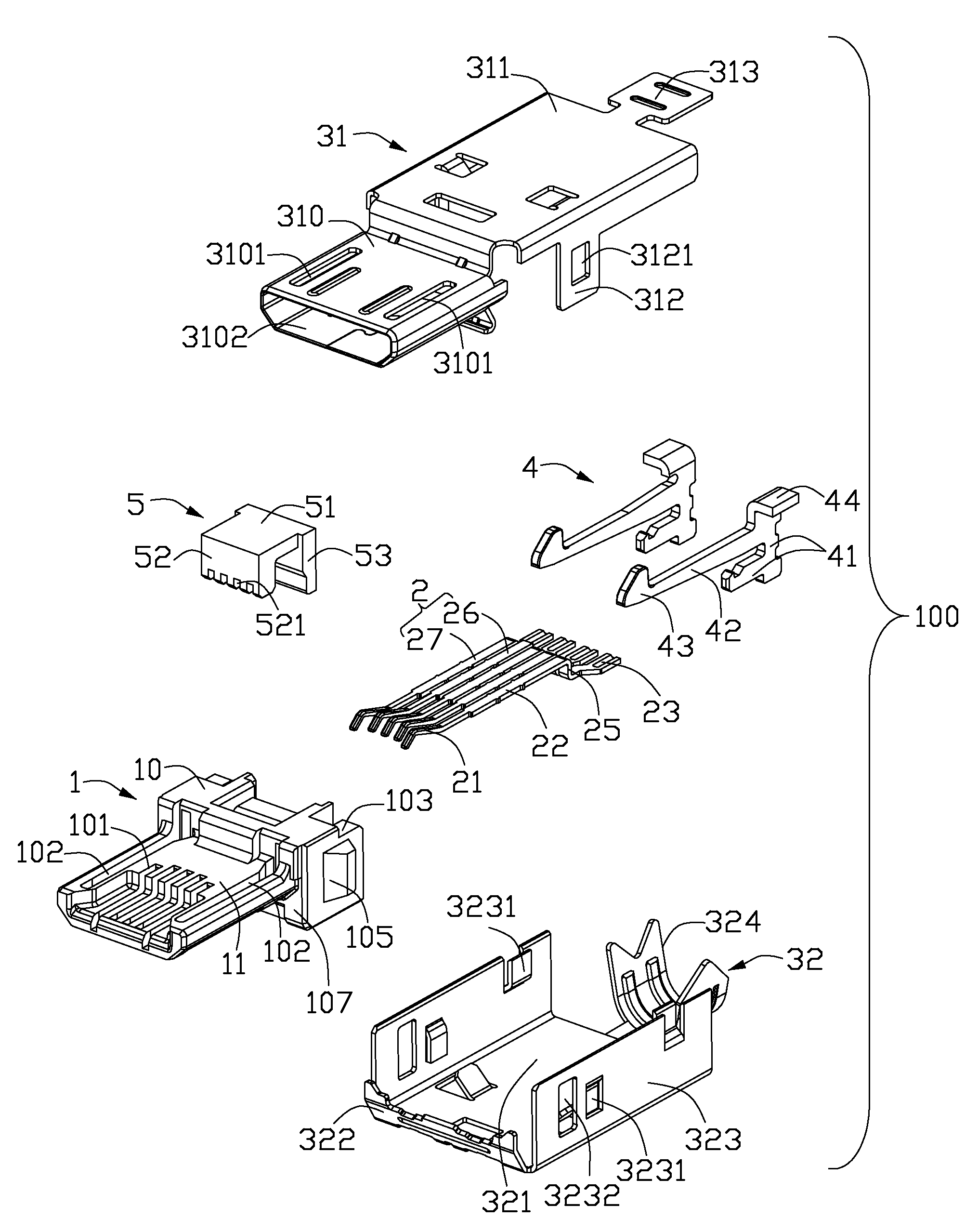
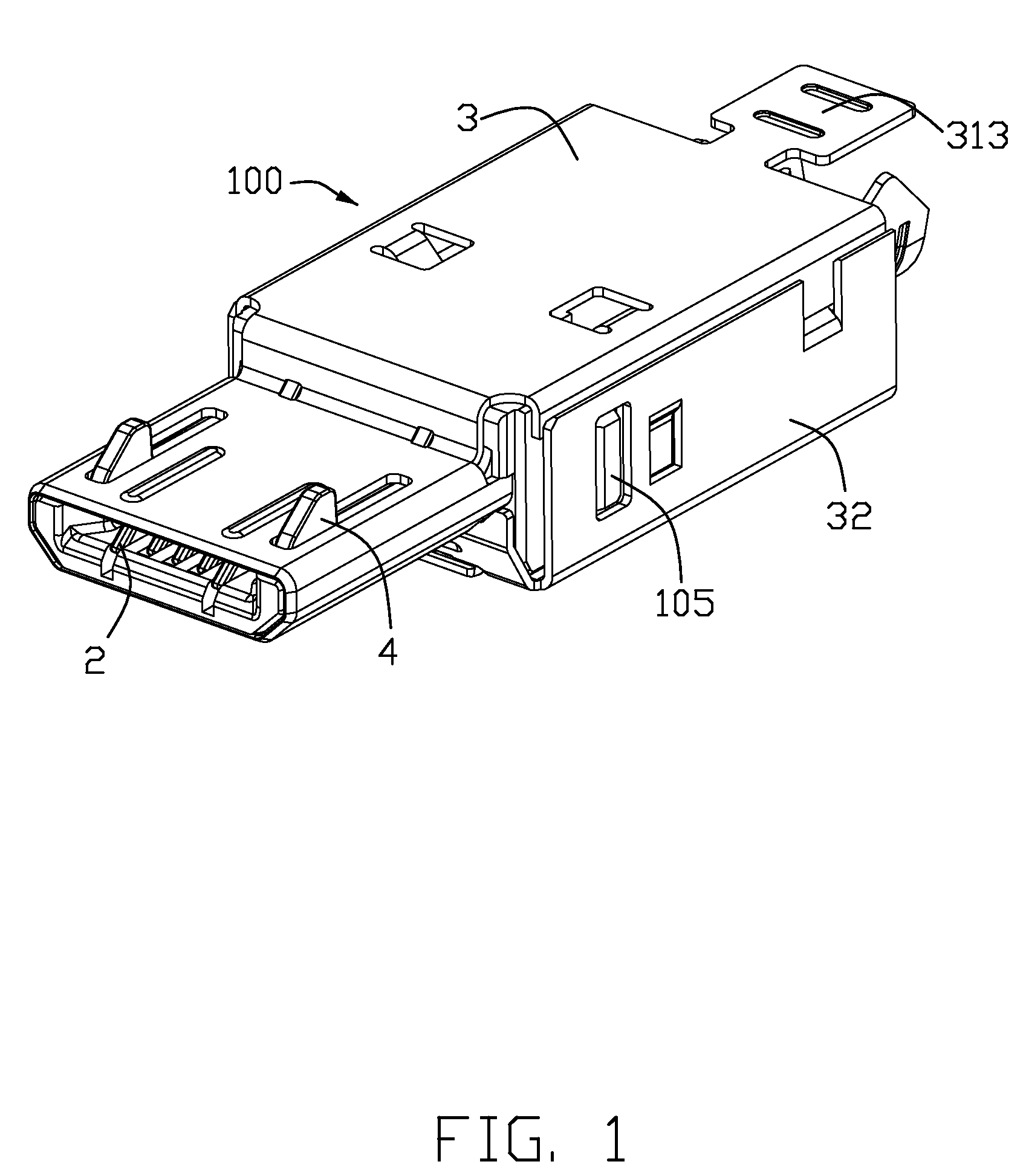
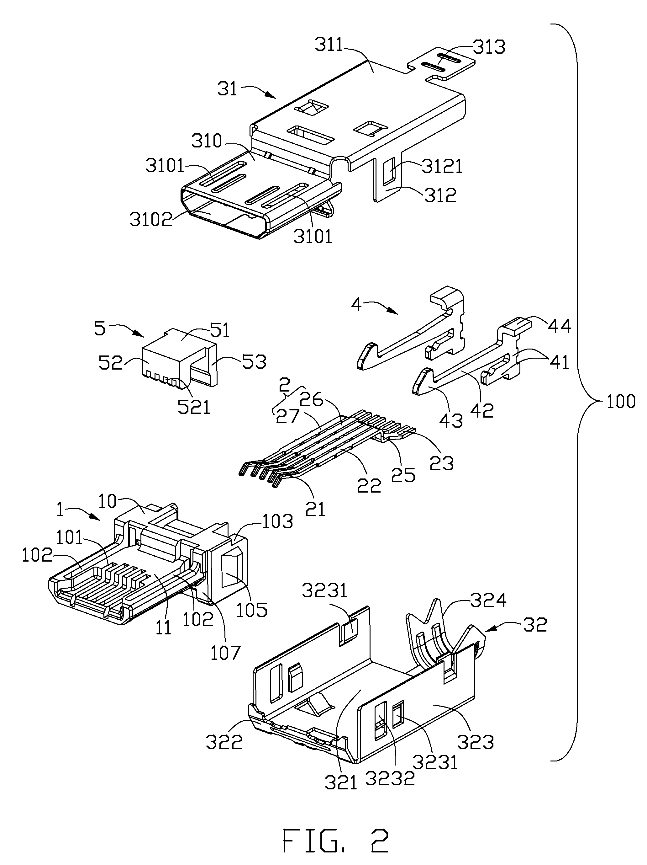
[0017]Referring to FIG. 1 to FIG. 4, a cable connector assembly 100 in accordance with the present invention, for example a Micro Universal Serial Bus (Micro USB) connector assembly, comprises an insulative housing 1 with a plurality of contacts 2 assembled therein, a shell 3 covering the insulative housing 1, a pair of latches 4 located at the opposite sides of the contacts 2, a spacer 5 holding on the insulative housing 1 and a cable 6 soldered on the contacts 2.

[0018]Referring to FIG. 2 to FIG. 4, the insulative housing 1 comprises a base portion 10 and a mating portion 11 extending forwardly from the base portion 10 in a front-to-rear direction. The mating portion 11 is alternatively named as a mating tongue 11. The base portion 10 comprises a front face 107 from which the mating portion 11 extends and a rear face 108 opposite to the front face 107. The base portion 10 has a plura...


PUM


Abstract

A cable connector assembly includes an insulative housing (1) with a number of passages (101), a shell (3) covering the insulative housing, a number of contacts (2) received in the passages of the insulative housing, and a spacer (5) assembled to the insulative housing. The contact includes a retaining portion (22), an extending portion (25) extending form the retaining portion and a soldering portion (23) bending from the end of the extending portion, and the all soldering portions are coplanar. The spacer includes a pressing portion (52) and a vertical wall (53). The pressing portion presses on the retaining portion of the contact, and the vertical wall engages with the soldering portion of the contact.

Description

BACKGROUND OF THE INVENTION[0001]1. Field of the Invention[0002]The present invention relates generally to a cable connector assembly, and particularly to a Micro Universal Serial Bus (Micro USB) connector assembly with an improved spacer.[0003]2. Description of Prior Art[0004]The cable connector assembly with an Universal Serial Bus (USB) connector has been used in electronics for years, such as cell phones, MP3, and DVD player. Nowadays, the size of cable connector assembly becomes much smaller and smaller to meet the miniaturization requirement of the electronic device, so a Micro Universal Serial Bus (Micro USB) connector assembly comes forth and is used widely.[0005]The Micro USB connector generally comprises an insulative housing, a plurality of contacts received in the housing, a pair of latches located at the opposite sides of the housing, and a top and bottom shells shielding the housing. The insulative housing forms a base portion with a plurality of terminal channels ther...

Claims


Application Information

Patent Timeline
Patent Type & Authority Patents(United States)
IPC IPC(8): H01R13/627
CPCH01R4/023H01R13/502H01R13/6273H01R13/648
Inventor KO, DAVID TSO-CHIN
Owner HON HAI PRECISION IND CO LTD
Why Eureka
Try Eureka