Eureka AIR delivers breakthrough ideas for toughest innovation challenges, trusted by R&D personnel around the world.

Floatable workstation

a workstation and floating technology, applied in the field of floating structures, can solve the problems of preventing or frustrating not being easily adjustable vertically, and affecting the ability of a boater

Inactive Publication Date: 2010-11-23
DOFFAY GERARD
View PDF21 Cites 22 Cited by
  • Summary
  • Abstract
  • Description
  • Claims
  • Application Information

AI Technical Summary

Benefits of technology

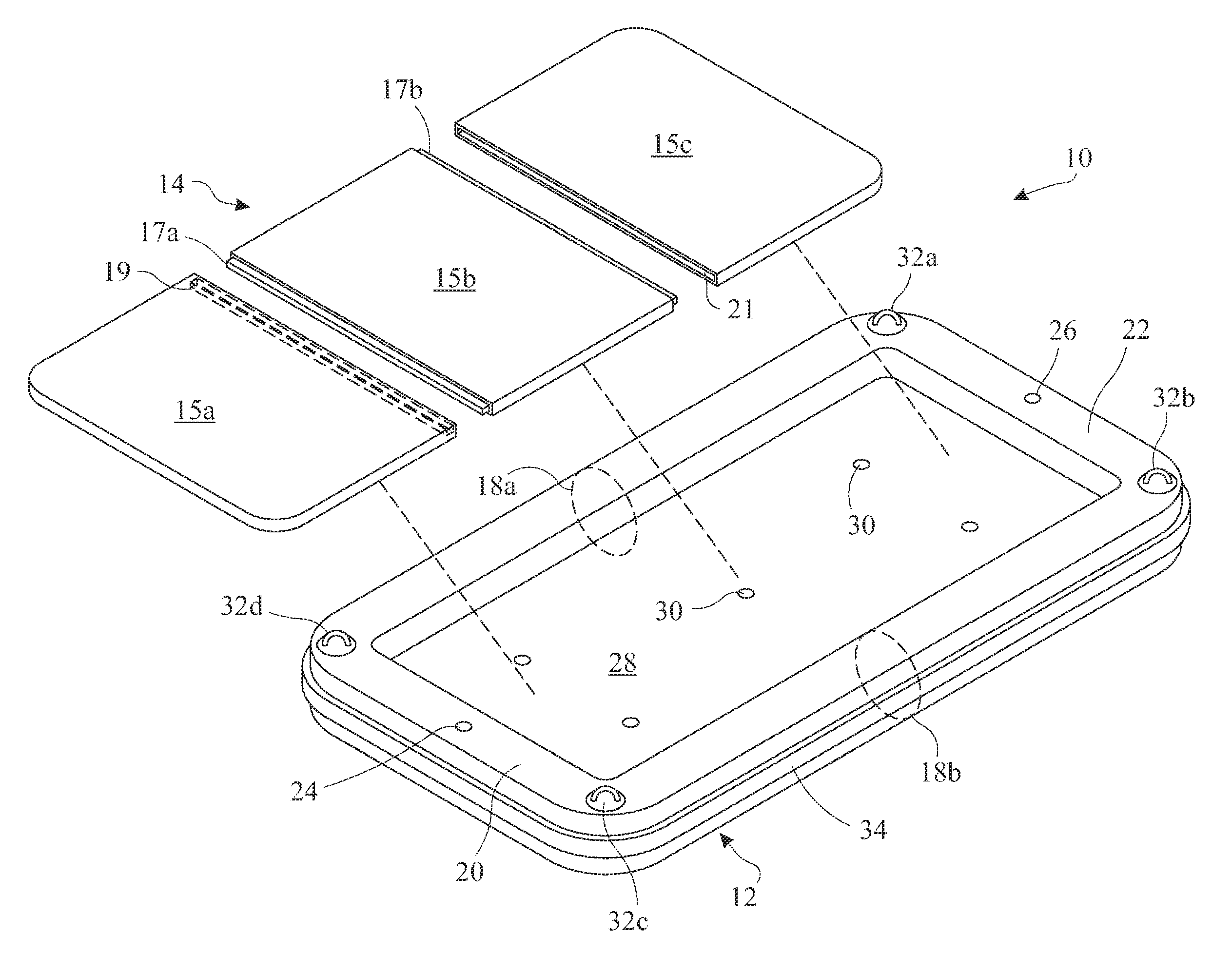
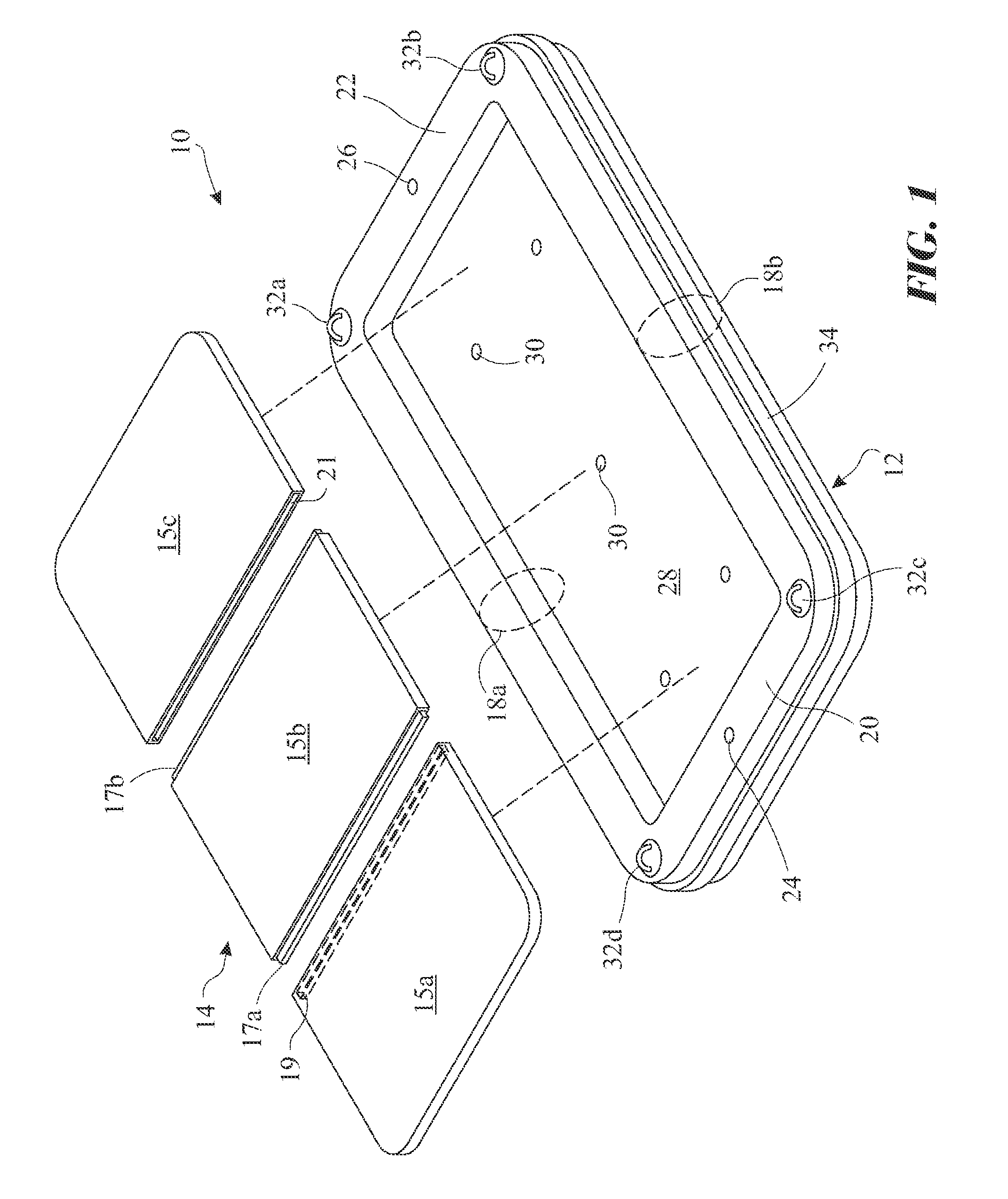
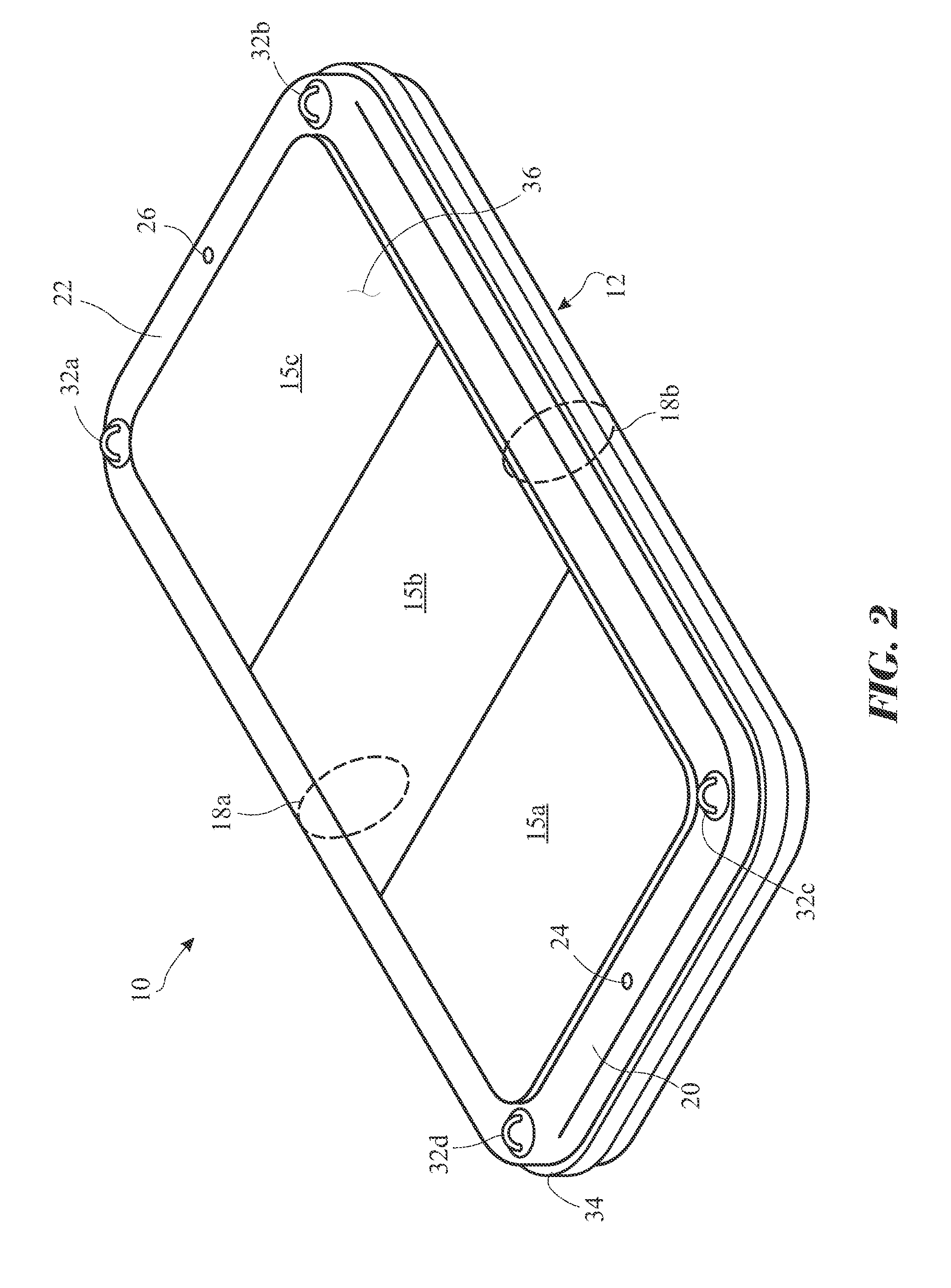
[0008]In accordance with one embodiment of the present invention, there is provided a floatable workstation comprising an inflatable tube including a floor, partitions disposed within an air receiving cavity of the tube forming a first inflatable chamber and a second inflatable chamber. A first valve is in fluid communication with the first inflatable chamber, and a second valve is in fluid communication with the second inflatable chamber. A plurality of cleats is disposed on the outer surface of the inflatable tube. A deck assembly is removeably attached to the inflatable tube, and a tether arrangement is releasably attached to the inflatable tube for securely positioning the floatable workstation alongside a vessel.
[0009]Advantageously, the floatable workstation further includes a bumper disposed completely around the outer perimeter of the inflatable tube. The bumper acts to protect the vessel and the floatable workstation should the floatable workstation come into contact with the side of the vessel. The floor includes a plurality of drainage holes for allowing water to drain through said holes.

Problems solved by technology

This can be frustrating to the boater because either the vessel must be moored on opposite sides of the floating dock, or a floating dock system must be constructed to completely surround the vessel, to permit the boater to gain access to all outer surfaces of the vessel.
Although some prior art floating structures are suitably designed for certain applications, many floating structures prevent or frustrate the ability of a boater or gain access to all outer surfaces of a vessel.
For example, many floating platforms are fixed in one position, and are not readily adjustable vertically.
In addition, many floating platforms are bulky, expensive and time consuming to manufacture and assemble, and are typically installed in one location and position for permanent use.

Method used


Image

  • Floatable workstation
  • Floatable workstation
  • Floatable workstation

Examples


Embodiment Construction

[0037]One or more embodiments of the present invention are disclosed herein. It will be understood that the claims and embodiments of the present invention are intended to be coextensive with each other, and that the embodiments are merely exemplary of the invention that may be embodied in various and alternative forms. It is noted that, according to common practice, the various features, elements and dimensions of particular embodiments are not to scale, and may be expanded, exaggerated or minimized for clarity. Thus, specific structural and functional details, dimensions, shapes, or configurations disclosed herein are not limiting but serve as a basis for teaching a person of ordinary skill in the art the described and claimed features of embodiments of the present invention.

[0038]The term “vessel” as used in this context will be construed to include any one of a boat, ship, submarine, cruise liner, watercraft, yacht, offshore installations, marine installations, an amphibious pla...


PUM


Abstract

A floatable workstation including an inflatable tube including optional partitions disposed internally within an air receiving cavity of the tube to form one or more inflatable chambers, each chamber including a valve for inflating the chambers. A plurality of corner fasteners is disposed on the corners of the inflatable tube or on a deck assembly. The deck assembly includes a plurality of deckboards assembled together to form a floorboard. The deckboards are assembled via an interlocking assembly feature. The deckboards are secured via a series of straps and D-rings. At least one deckboard may include a receptacle for holding tools or a bucket. A tether arrangement is attached to the floatable workstation for securely positioning the floatable workstation alongside a vessel allowing one or more persons to stand on the workstation to perform maintenance on the outer surfaces of a vessel. The tether arrangement includes tethers, a means for fastening the tethers to the handles, and suction mechanisms.

Description

CROSS-REFERENCE TO RELATED APPLICATION[0001]This application is a Continuation-In-Part, claiming the benefit of co-pending United States Non-Provisional patent application Ser. No. 12 / 050,725, filed on Mar. 18, 2008 which claims priority to U.S. Provisional Patent Application Ser. No. 60 / 951,491, filed on Jul. 24, 2007, both of which are incorporated herein in their entirety.FIELD OF INVENTION[0002]The present invention relates to floating structures, and more particularly to an inflatable workstation including a tether arrangement for positioning the inflatable workstation alongside a vessel thereby allowing one or more persons to stand on the workstation while working on the outer surface of the vessel.BACKGROUND OF THE INVENTION[0003]Floating structures generally include floating docks, decks, platforms, or the like. Many floating structures are either inflatable, or are constructed from durable buoyant materials both of which are designed to support the weight of one or more ind...

Claims


Application Information

Patent Timeline
IPC IPC(8): B63B35/58
CPCB63B35/36B63B35/58B63B59/00
Inventor DOFFAY, GERARD
Owner DOFFAY GERARD
Why Eureka
Eureka Blog
Learn More