Glass cutting method
a glass and plate technology, applied in glass making apparatus, manufacturing tools, instruments, etc., can solve the problems of glass cullet both, cracks in the vicinity of the mother material, and remains unsolved, so as to reduce physical damage, reduce cracks in glass, and reduce the effect of cracks
- Summary
- Abstract
- Description
- Claims
- Application Information
AI Technical Summary
Benefits of technology
Problems solved by technology
Method used
Image
Examples
example 1
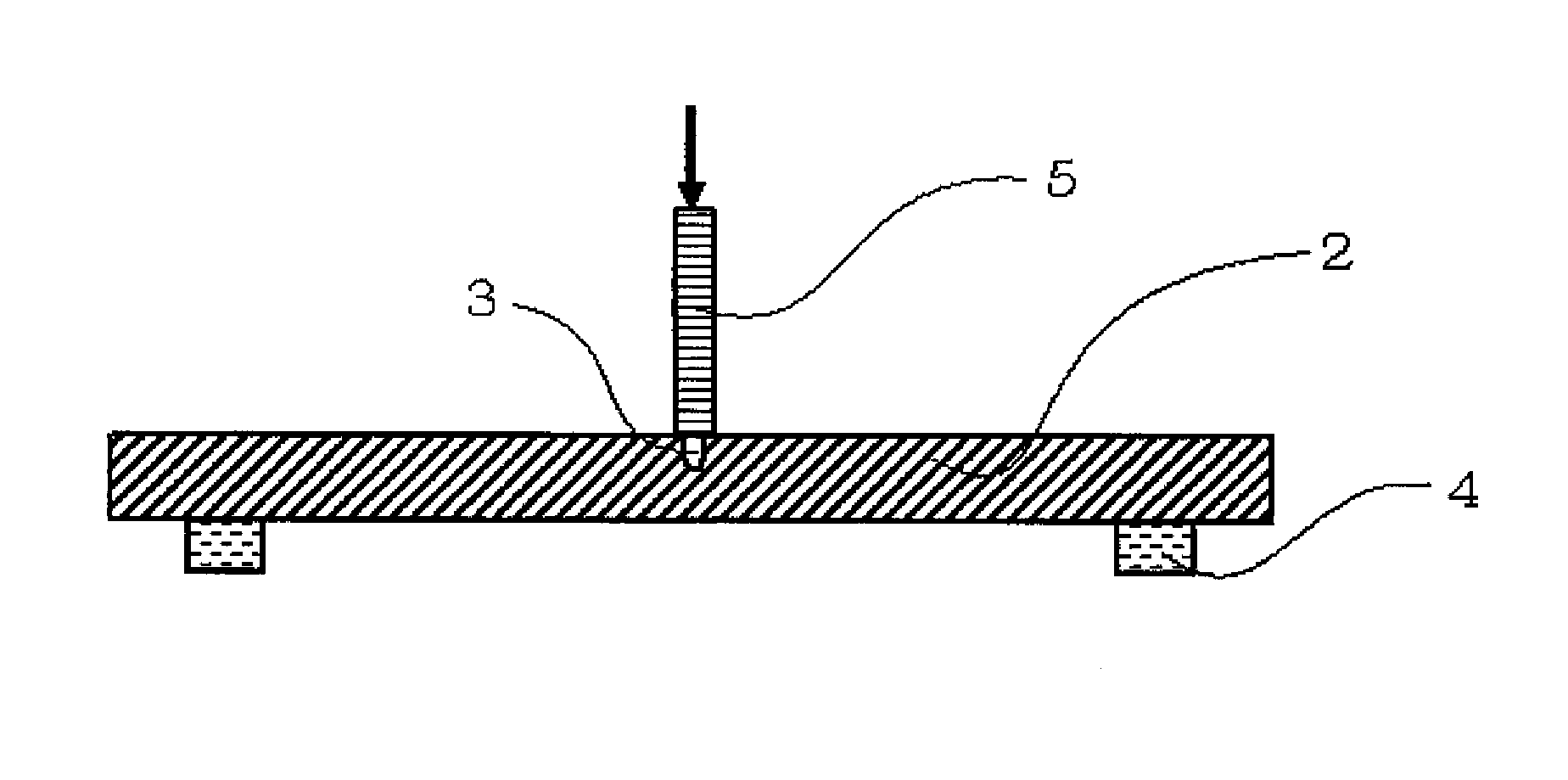
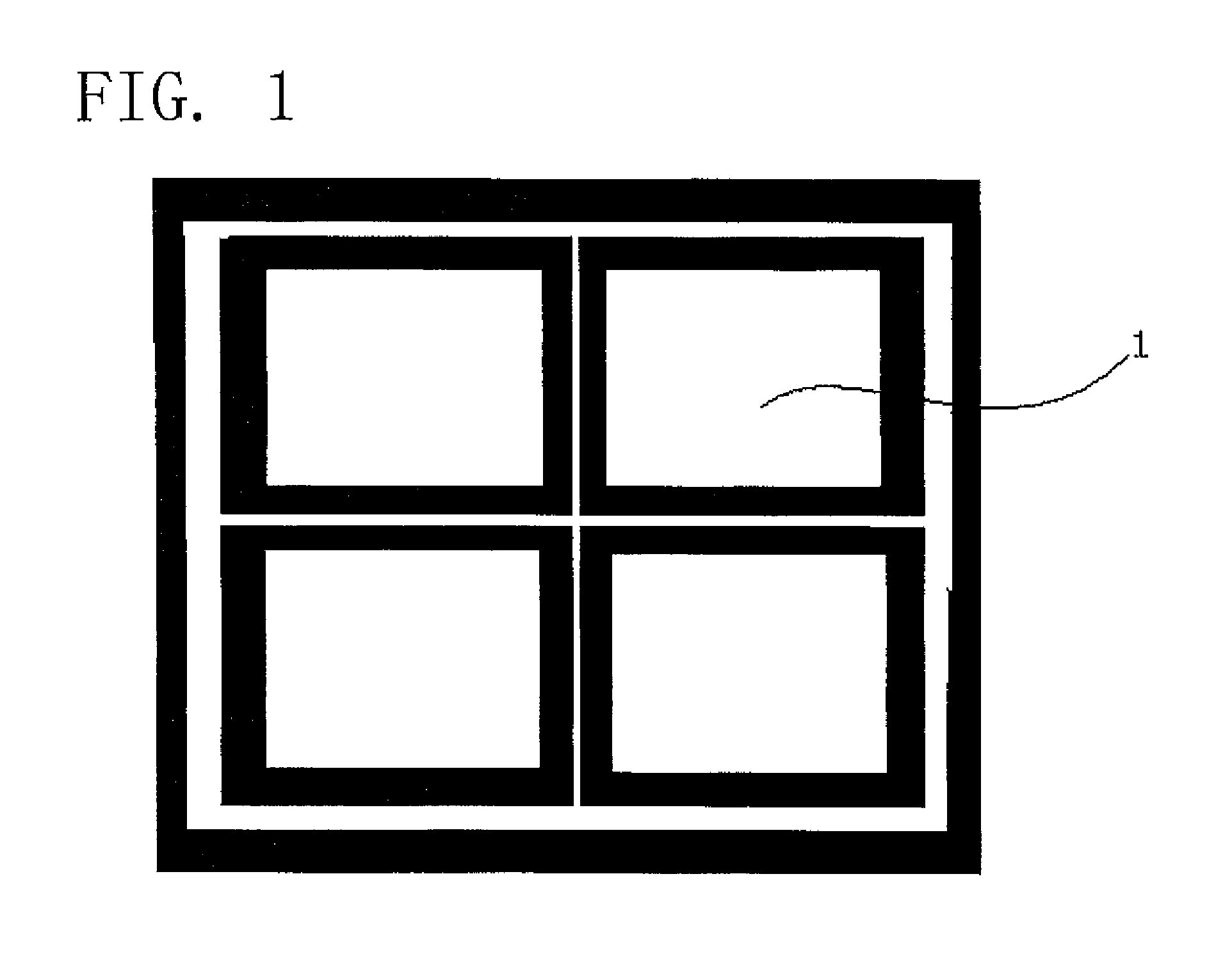
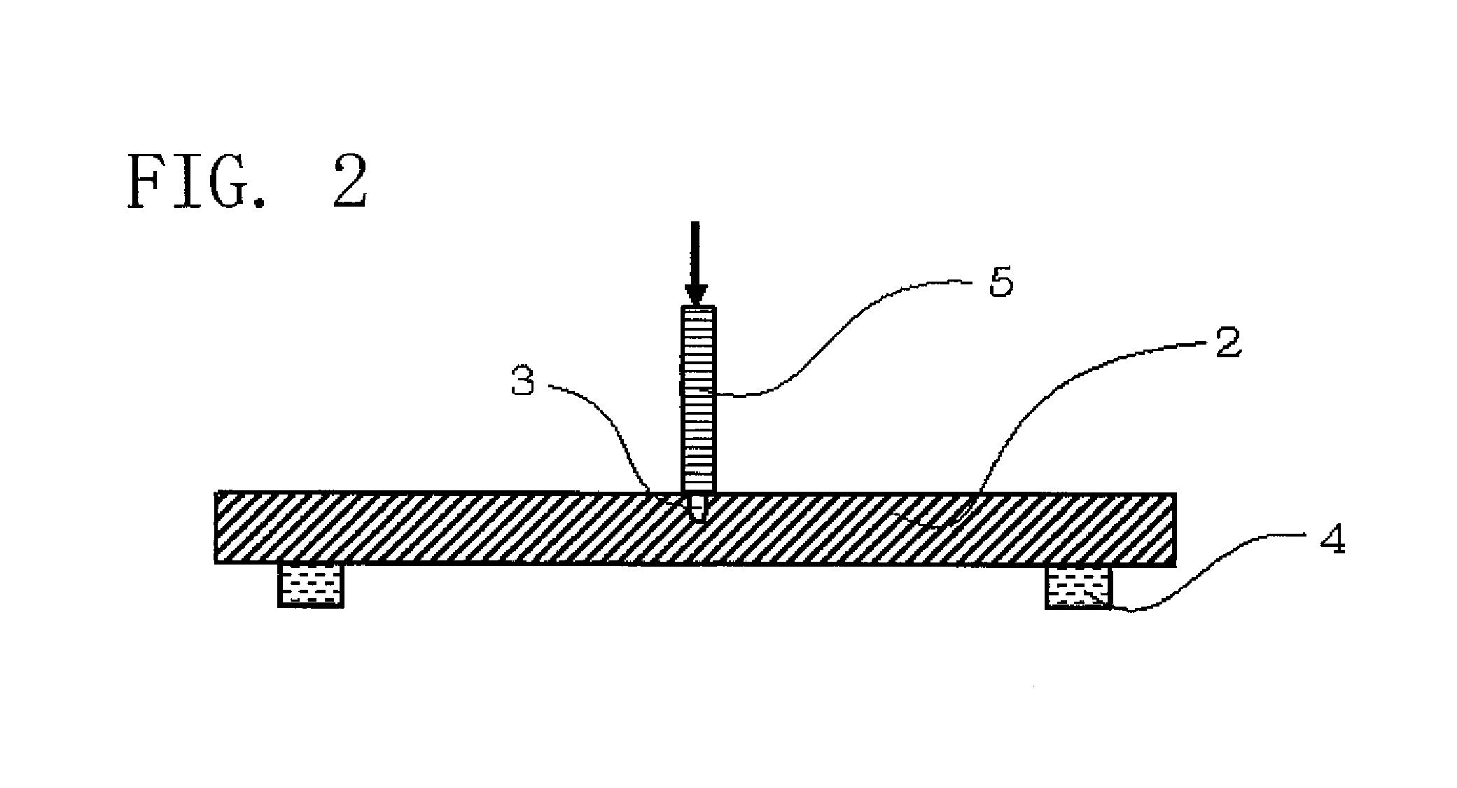
[0052]Two liquid crystal display glass sheets of 400 mm by 500 mm by 0.7 mm in size were adhered to each other with a sealing agent. Scribe lines of about 0.05 mm in depth were formed on both surfaces thereof with a diamond cutter. One scribe line was formed so as to be directly below the other scribe line. Then, a thickness of the adhered glass was reduced in a chemical treatment by a thickness of the order of 0.4 mm.
[0053]A chemical treatment was conducted in the following conditions:
[0054](1) A chemical treatment solution was an aqueous solution containing 5% hydrofluoric acid, 10% hydrochloric acid and 5% nitric acid;
[0055](2) The adhered glass was immersed in the chemical treatment solution with the glass oriented in a direction normal to a surface of the solution;
[0056](3) Bubbles were generated from the bottom of a chemical treatment solution reservoir, wherein bubbles flew substantially in parallel to a glass surface; and
[0057](4) After the chemical treatment ended, a pressu...
example 2
[0070]Two liquid crystal display glass sheets of 400 mm by 500 mm by 0.7 mm in size were adhered to each other with a sealing agent. Masking was applied on both surfaces and a side surface of the adhered glass. A laminate film was used in masking. Then the laminate film used in the masking was peeled off as a band with a width of 0.2 mm. The peeled portion is a portion in which a slit is formed. The peeling-off of the laminate film was performed on both surfaces of the adhered glass. The peeling-off of the laminate film on the lower surface of the adhered glass was performed directly below the portion on the upper surface thereof in which the peeling off of the laminate film was performed.
[0071]Then a chemical treatment was performed. A chemical treatment solution and conditions for bubble generation in the chemical treatment solution were similar to those in Example 1. Immersion of the adhered glass in the chemical treatment solution was performed so that the surface of the chemica...
example 3
[0074]A glass substrate was cut by means of a method different from that of Example 2 only in respect of a peeling method of a laminate film. The peeling-off of the laminate films on the upper surface and the lower surface of the adhered glass substrate was in parallel to each other. In addition, the peeling-off of the laminate films on the upper surface and the lower surface of the adhered glass substrate was performed at a spacing of 0.2 mm between peeling bands thereof as viewed from above.
[0075]Observation was performed on the glass substrate obtained in Example 3 under a microscope. As a result, it was confirmed that cracking at the end surface of the glass substrate and cracking at the cutting face thereof were suppressed. The cutting face was confirmed to be smooth. The glass substrate was observed from a side thereof under a microscope. FIG. 8 is a schematic side view showing the glass substrate. It is found that a glass cutting portion was formed step-wise.
PUM
| Property | Measurement | Unit |
|---|---|---|
| size | aaaaa | aaaaa |
| size | aaaaa | aaaaa |
| size | aaaaa | aaaaa |
Abstract
Description
Claims
Application Information
 - R&D
- Intellectual Property
- Life Sciences
- Materials
- Tech Scout
- Unparalleled Data Quality
- Higher Quality Content
- 60% Fewer Hallucinations
Browse by: Latest US Patents, China's latest patents, Technical Efficacy Thesaurus, Application Domain, Technology Topic, Popular Technical Reports.
© 2025 PatSnap. All rights reserved.Legal|Privacy policy|Modern Slavery Act Transparency Statement|Sitemap|About US| Contact US: help@patsnap.com


