Eureka AIR delivers breakthrough ideas for toughest innovation challenges, trusted by R&D personnel around the world.

System and method for remote battery sensing

a remote battery and sensing circuit technology, applied in the field of can solve the problems of affecting charger performance, voltage drop across the cable, and substantially different voltages of the sensing circuitry, so as to reduce the disadvantages and eliminate the problems of remote battery sensing and charging.

Active Publication Date: 2010-11-16
DELL PROD LP
View PDF7 Cites 13 Cited by
  • Summary
  • Abstract
  • Description
  • Claims
  • Application Information

AI Technical Summary

Benefits of technology

[0010]In accordance with the teachings of the present disclosure, disadvantages and problems associated with remote battery sensing and charging have been substantially reduced or eliminated.

Problems solved by technology

However, because many write caches are implemented as volatile memory (e.g., memory which loses its data when power is removed), battery backup power may be used to maintain data stored in write caches until such time as main power can be restored and the data flushed to persistent storage.
However, one disadvantage of remotely managing the charging of a battery is that the voltage sensed by the sensing circuitry may be substantially different than the voltage actually present at the battery.
This may occur as a result of parasitic impedance of the cable coupling the sensing circuitry to the battery, leading to a voltage drop across the cable.
In some applications, this voltage drop may be as much as 10-20% of the maximum voltage of the battery, and thus can lead to inconsistent readings of battery voltage which may in turn negatively effect charger performance.
Numerous solutions to account for the voltage drop across the cable have been attempted, but most still have significant disadvantages and problems.
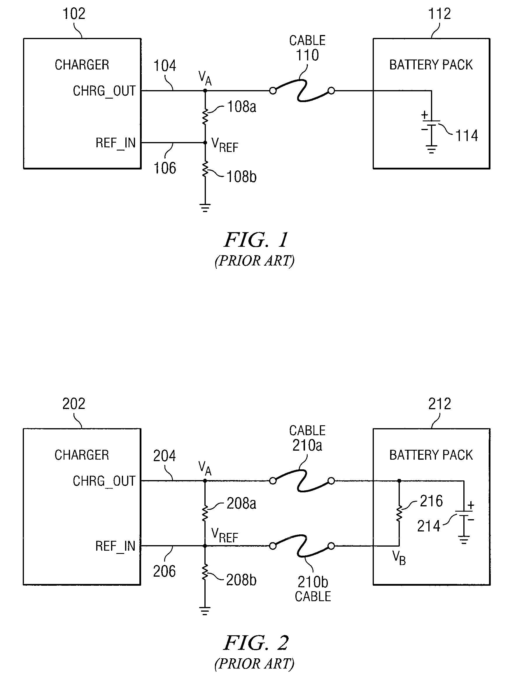
Thus, while the approach in FIG. 2 mitigates the effect of the parasitic impedance of cable 210a, it does not completely eliminate it.
Another solution practically eliminates the effect of the voltage drop across cable 210a, but this solution introduces problems of its own.
However, this solution is not practical.
Because ground voltage would likely be lower than the threshold voltage needed to indicate a fully-charged battery, a ground voltage received on REF_IN pin 206 may cause one or more problems.
This could result in charger instability and damage to the charger.

Method used


Image

  • System and method for remote battery sensing
  • System and method for remote battery sensing
  • System and method for remote battery sensing

Examples


Embodiment Construction

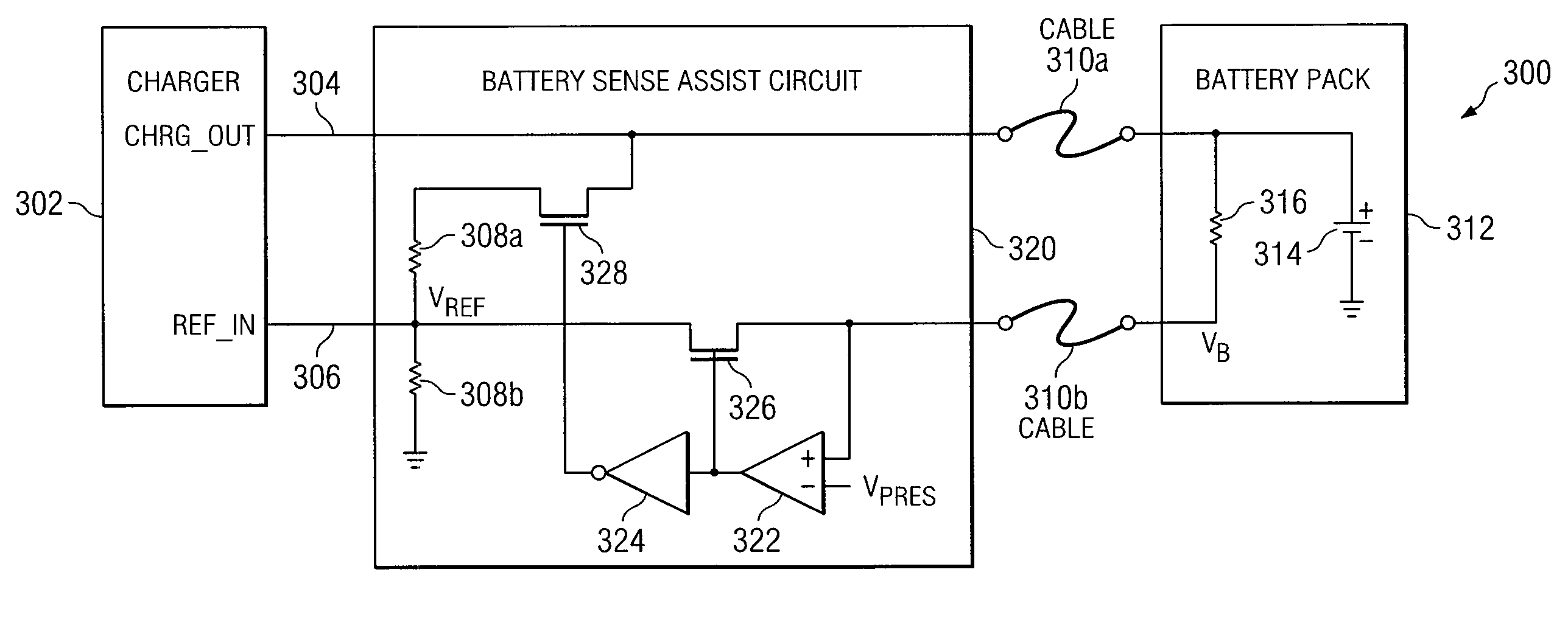
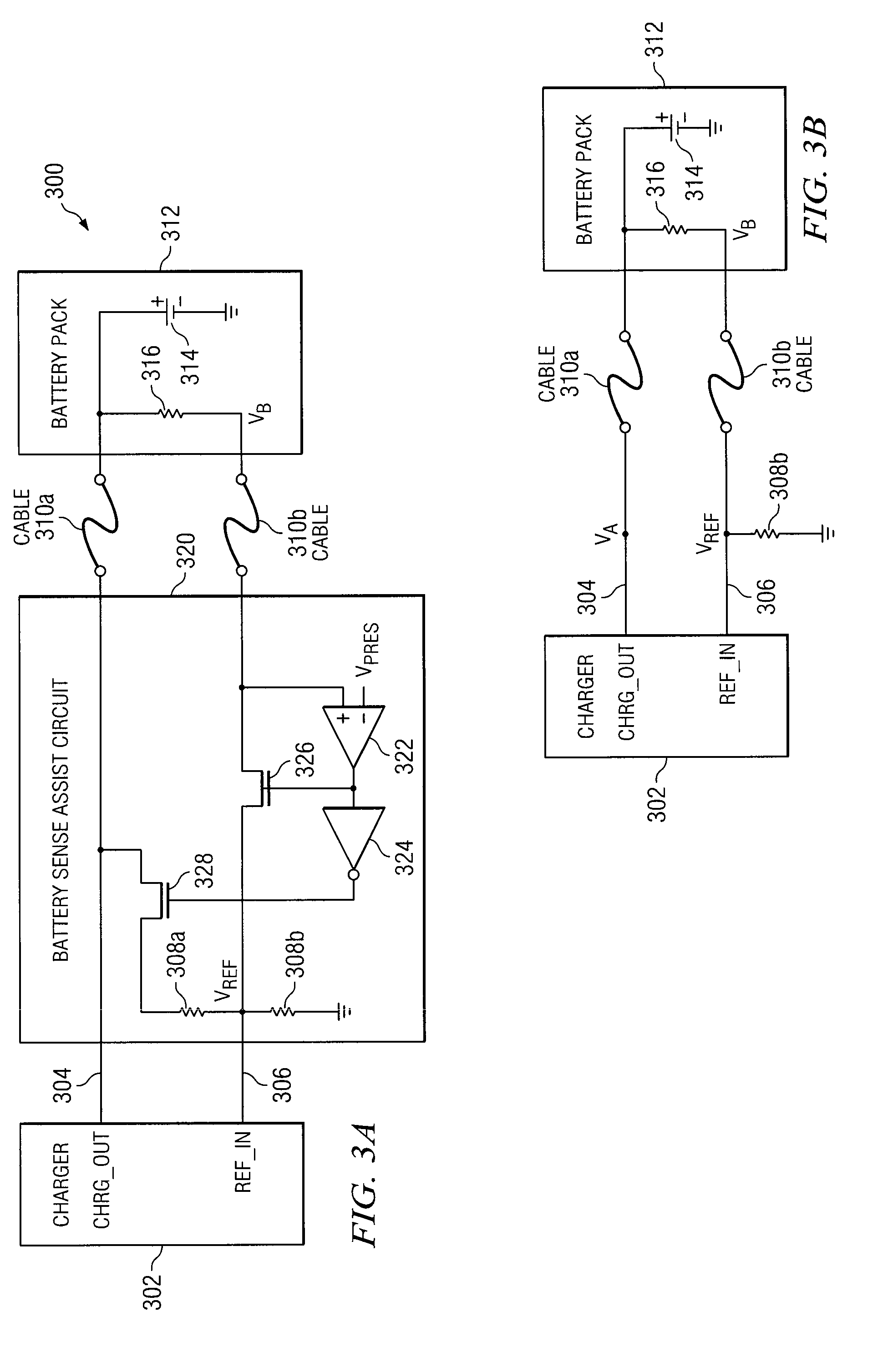
[0022]Preferred embodiments and their advantages are best understood by reference to FIGS. 3A through 4, wherein like numbers are used to indicate like and corresponding parts.

[0023]For the purposes of this disclosure, an information handling system may include any instrumentality or aggregate of instrumentalities operable to compute, classify, process, transmit, receive, retrieve, originate, switch, store, display, manifest, detect, record, reproduce, handle, or utilize any form of information, intelligence, or data for business, scientific, control, entertainment, or other purposes. For example, an information handling system may be a personal computer, a PDA, a consumer electronic device, a network storage device, or any other suitable device and may vary in size, shape, performance, functionality, and price. The information handling system may include memory, one or more processing resources such as a central processing unit (CPU) or hardware or software control logic. Additiona...


PUM


Abstract

Systems and methods for remote battery sensing and charging are disclosed. A method may include determining whether a charge output of a battery charger is electrically coupled to a rechargeable battery, wherein the charge output is configured to charge the rechargeable battery. The method may also include electrically coupling a terminal of the rechargeable battery to a reference voltage input of the battery charger in response to determining the charge output is electrically coupled to the rechargeable battery, wherein the battery charger is configured to determine whether the rechargeable battery is to be charged based on the reference voltage input voltage. The method may further include electrically coupling the reference voltage input to the charge output in response to determining the charge output is not electrically coupled to the rechargeable battery.

Description

TECHNICAL FIELD[0001]The present disclosure relates in general to battery sensing and charging, and more particularly to a system and method for remote battery sensing and charging.BACKGROUND[0002]As the value and use of information continues to increase, individuals and businesses seek additional ways to process and store information. One option available to users is information handling systems. An information handling system generally processes, compiles, stores, and / or communicates information or data for business, personal, or other purposes thereby allowing users to take advantage of the value of the information. Because technology and information handling needs and requirements vary between different users or applications, information handling systems may also vary regarding what information is handled, how the information is handled, how much information is processed, stored, or communicated, and how quickly and efficiently the information may be processed, stored, or commun...

Claims


Application Information

Patent Timeline
IPC IPC(8): H02J7/04H02J7/16
CPCH02J7/0047H02J7/0048
Inventor WANG, LIGONGCHIASSON, SHANENUNNA, ANAND
Owner DELL PROD LP
Why Eureka
Eureka Blog
Learn More