Water power generator

Inactive Publication Date: 2010-11-09
LOMERSON SR ROBERT B +1
View PDF69 Cites 2 Cited by
  • Summary
  • Abstract
  • Description
  • Claims
  • Application Information

AI Technical Summary

Benefits of technology

[0012]In accordance with still another aspect of the present invention the valved inlet allows the water level in the harborage to rise rapidly.
[0013]In accordance with another aspect of the present invention the valved outlet allows the water level in the harborage to fall rapidly.
[0020]The present invention also provides an apparatus for raising and lowering a vessel hull. The apparatus comprises a harborage, with the vessel hull located therein. The vessel hull is capable of moving up and down in the harborage. A water supply communicates with the harborage through a supply valve. The water supply provides water to the harborage to a high level. A water lift comprises a bottom with an inclined side wall that extends up and radially out from the bottom. The water lift forms an interior. The water lift rotates. A drainage area is also provided. A drain outlet allows communication between the harborage and the water lift interior, wherein water in the interior of the rotating lift moves up the side wall to a higher elevation than the bottom and exits the lift into the drainage area.

Problems solved by technology

The burning of such fuels produces harmful emissions that are both difficult and expensive to either contain, or remove, from the exhaust gasses.
Also, the transport of these fuels from point of origin, to point of processing (such as refining crude oil), to point of use not only requires the expenditure of additional energy, but is inefficient, costly, potentially hazardous and creates further harmful emissions.
The political environments of many producing areas, such as the Middle East, Venezuela, Russia and Nigeria have been unstable in recent history.
However, nuclear power plants are expensive to build and pose security problems.
Also, the disposal and storage of spent nuclear fuel is an expensive and a highly contentious problem.
Public perception of nuclear power plants is largely negative.
At present, solar panels are high in cost, very low in efficiency and are unusable at night and on cloudy or stormy days.
Wind power, while available, is also dependent on the weather as well as being inefficient and relatively expensive.
The continuous opening and closing of the flood gates creates problems.
Also, the efficiency is somewhat low because only part of the tidal rise and fall can be used.
Marine life is adversely impacted as well.

Method used


Image

  • Water power generator
  • Water power generator
  • Water power generator

Examples


Embodiment Construction

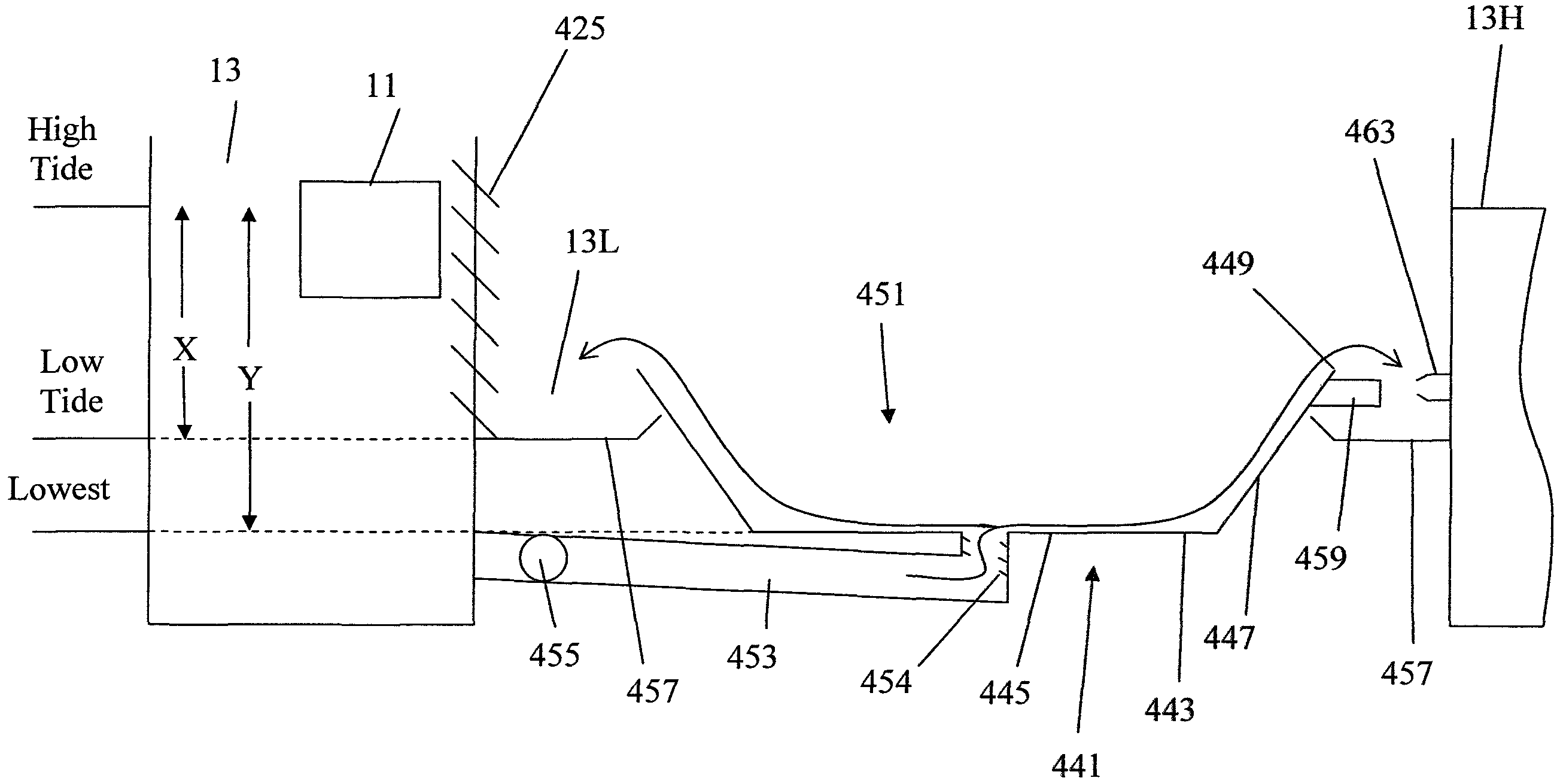
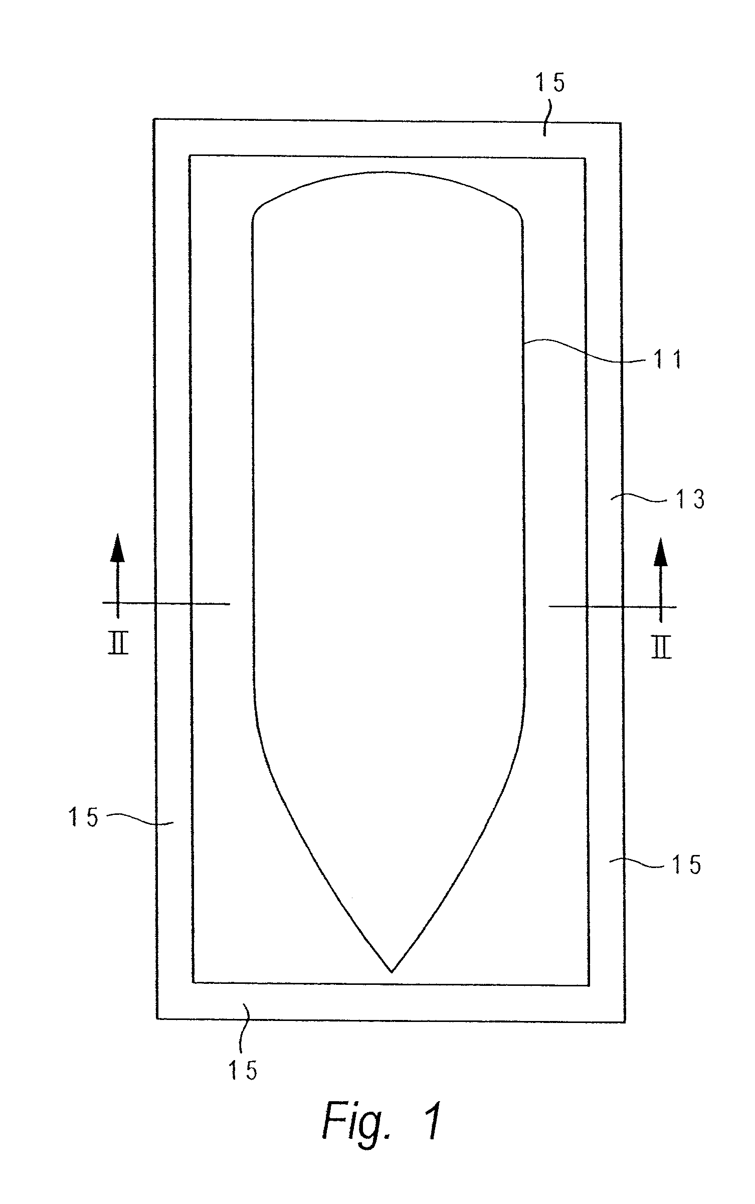
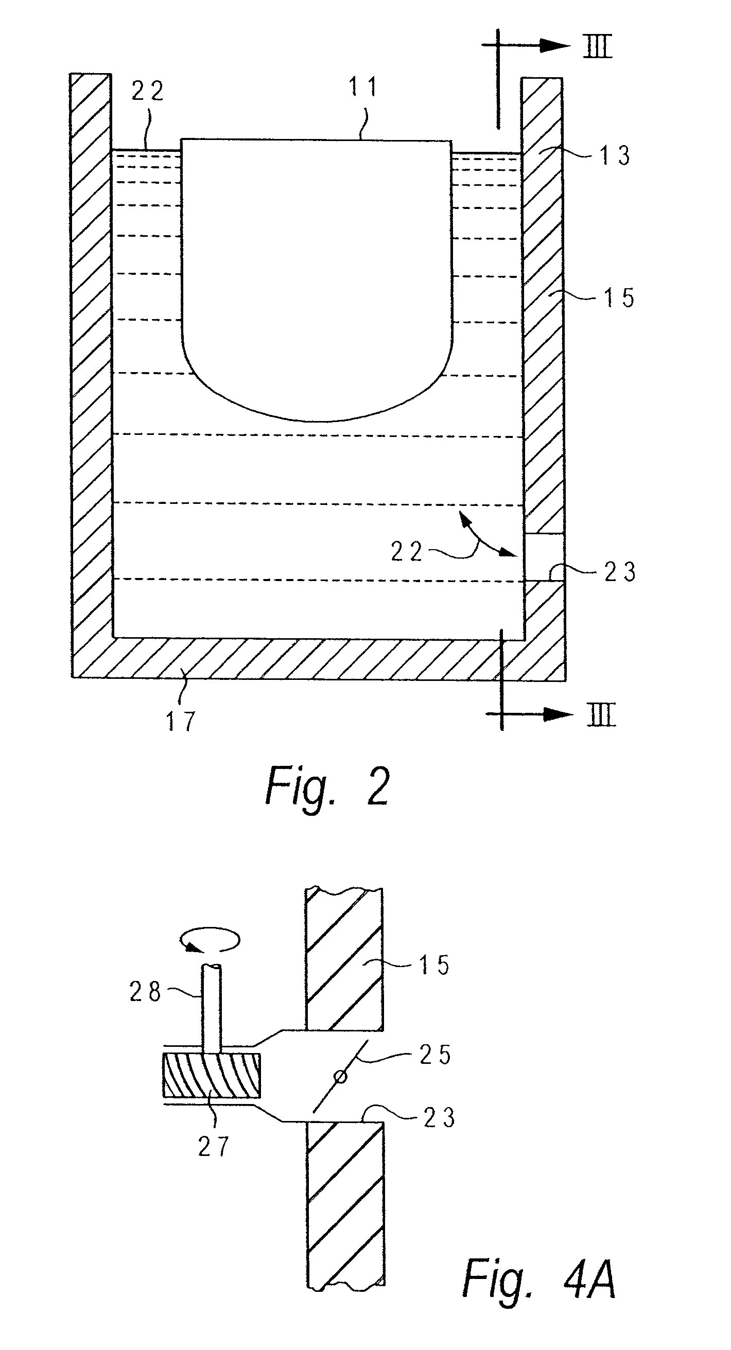
[0059]The present invention provides a way to extract energy from the rise and fall of the tides as well as water head. A vessel hull is provided in a protective harborage enclosure. Water from the tides is admitted into the harborage so as to raise the vessel hull and released so as to lower the vessel hull. Mechanical converters are attached between the movable hull and a fixed object, such as the harborage itself; the converters convert the vertical movement of the hull into mechanical energy such as pressurized fluid, which is used to power various devices such as an electrical generator. The electricity can be transmitted over conventional power lines to users.

[0060]Alternatively, a harborage or lock is provided in a situation where water head can be found, such as by a dam in a river. The vessel hull rises and falls within the harborage; that motion is converted into mechanical energy, such as pressurized fluid, which can be used for a variety of applications, such as rotating...


PUM


Abstract

A tidal power generator has a floating vessel hull that is subject to rising and falling water levels so that the hull moves vertically up and down. Linear-to-rotary converters are coupled between the vessel hull and a fixed object. The converters allow the hull to move vertically while constraining the horizontal movement of the hull. The converters convert the vertical movement of the hull into rotary movement, which is then used to drive an electrical generator. A harborage is provided to protect the hull and the converters and to regulate the water level for the vessel hull as well as become a fixed object relative to the vessel from which a change in relative position causes power to be developed. If the hull is subject to tidal variations, vertical movement of the hull can be desynchronized from the tidal variations so as to store energy during slack tides.

Description

[0001]This application is a continuation-in-part application of application Ser. No. 11 / 715,003, filed Mar. 7, 2007, now U.S. Pat. No. 7,432,612 which application was a continuation-in-part application of application Ser. No. 11 / 448,503, filed Jun. 7, 2006, now U.S. Pat. No. 7,199,483 which was a continuation-in-part patent application of application Ser. No. 11 / 064,579, filed Feb. 24, 2005, now U.S. Pat. No. 7,075,190.FIELD OF THE INVENTION[0002]The present invention relates to extracting energy from tides on water bodies and from water head.BACKGROUND OF THE INVENTION[0003]Most of the electricity generated in the United States requires hydrocarbon-based fuel sources such as coal, oil or natural gas. The burning of such fuels produces harmful emissions that are both difficult and expensive to either contain, or remove, from the exhaust gasses. Also, the transport of these fuels from point of origin, to point of processing (such as refining crude oil), to point of use not only requi...

Claims


Application Information

Patent Timeline
IPC IPC(8): F03B13/18H02P9/04F03B13/12F03B13/10F03B17/02
CPCF03B13/1815F03B13/262Y02E10/38Y02E10/30
Inventor LOMERSON, SR., ROBERT B.LOMERSON, JR., ROBERT B.
Owner LOMERSON SR ROBERT B
Why Eureka
Try Eureka