Power generating device by using wave energy

A technology of wave energy and hydraulic devices, which is applied in the direction of ocean energy power generation, engine components, machines/engines, etc., can solve problems such as damage to the marine ecological environment, easy corrosion of equipment, limited air pressure, etc., to avoid energy waste, avoid pollution, Effect of reducing wear and corrosion

Inactive Publication Date: 2010-12-29
NANTONG BEICHENG SCI & TECH ENTREPRENEURIAL MANAGEMENT
View PDF1 Cites 10 Cited by
  • Summary
  • Abstract
  • Description
  • Claims
  • Application Information

AI Technical Summary

Problems solved by technology

[0002] With the development of social economy, human beings' demand for energy is increasing day by day, while global oil and coal resources are decreasing day by day. In order to maintain the development and progress of human society, new energy sources must be vigorously developed. In nature, the ups and downs never stop There is a huge amount of energy hidden in the sea. Using tidal energy to generate electricity has always been the goal that people are pursuing. The power plants built in the existing tidal power generation method are easy to corrode, and at the same time cause certain damage to the marine ecological environment; for example, the patent number is 200810026612.2 A patent for a tidal wave energy power generation system. There is an inverted cylinder fixed in the sea. The mouth of the cylinder is always submerged under the sea surface. Due to the low density of the air, it is easy to compress and the air pressure is small, especially at ebb tide. , the distance between the sea level and the top of the inverted cylinder is larger, the air pressure generated is more limited, and energy consumption is wasted

Method used


Image

  • Power generating device by using wave energy
  • Power generating device by using wave energy
  • Power generating device by using wave energy

Examples


Embodiment Construction

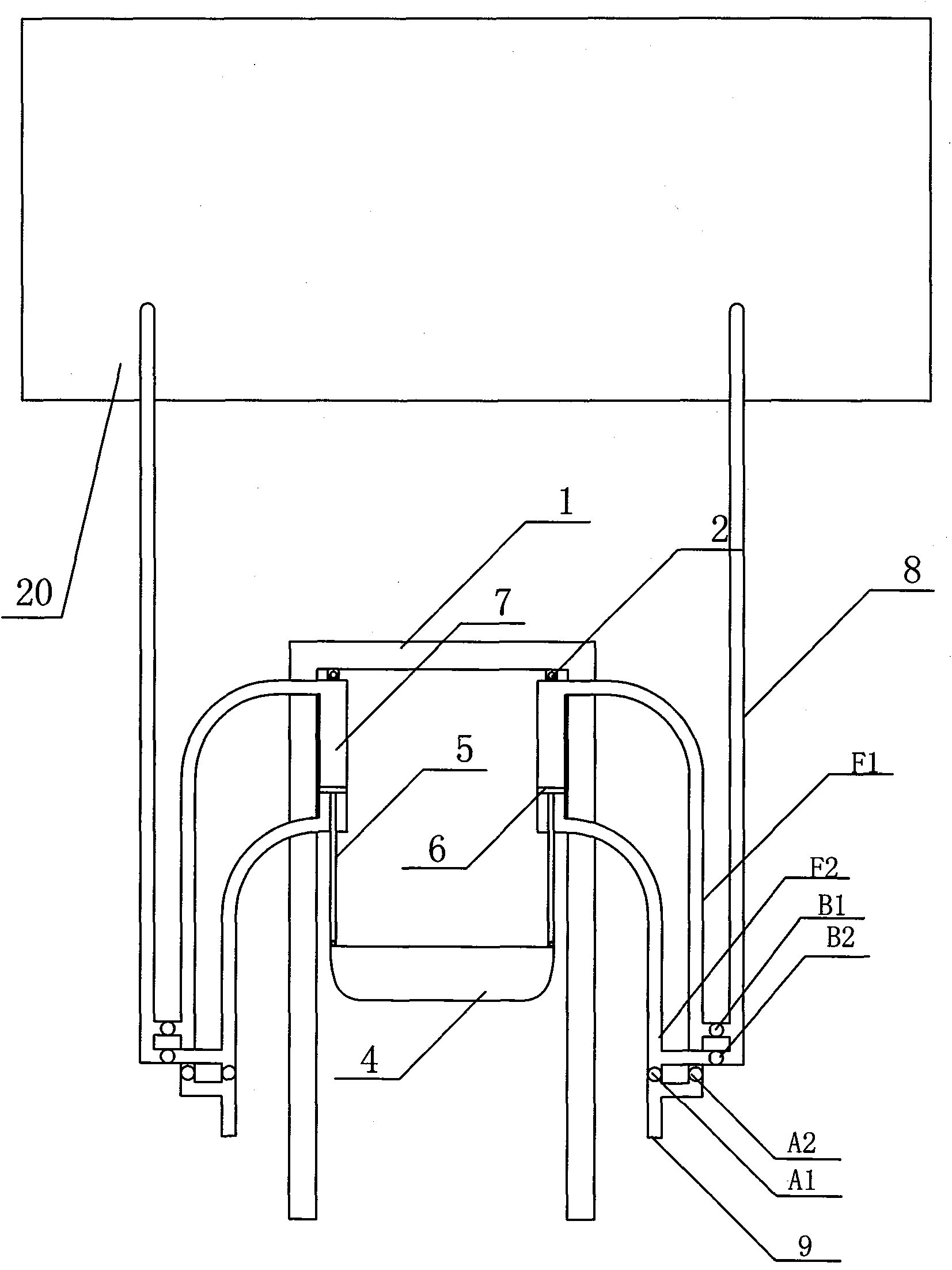
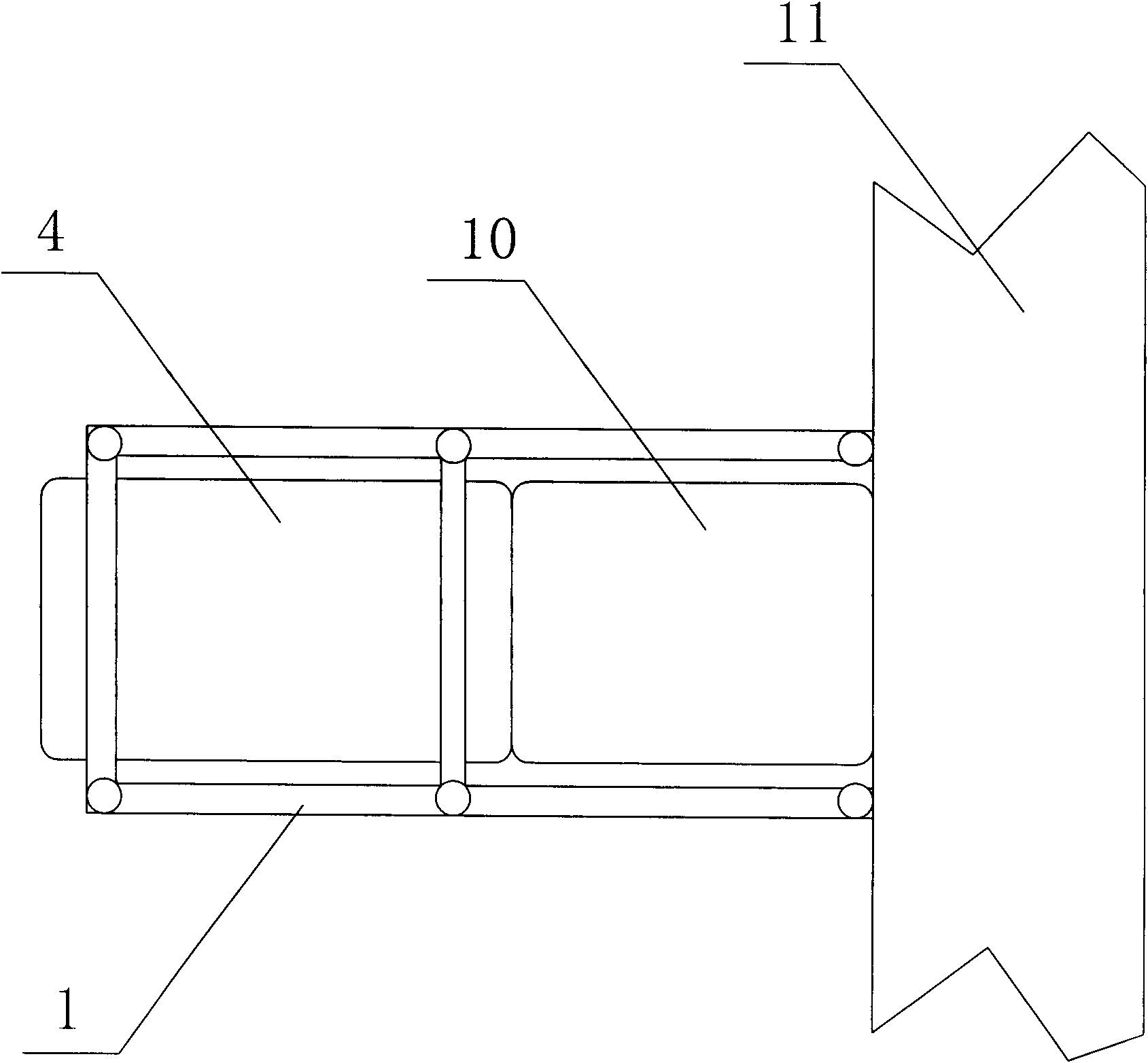
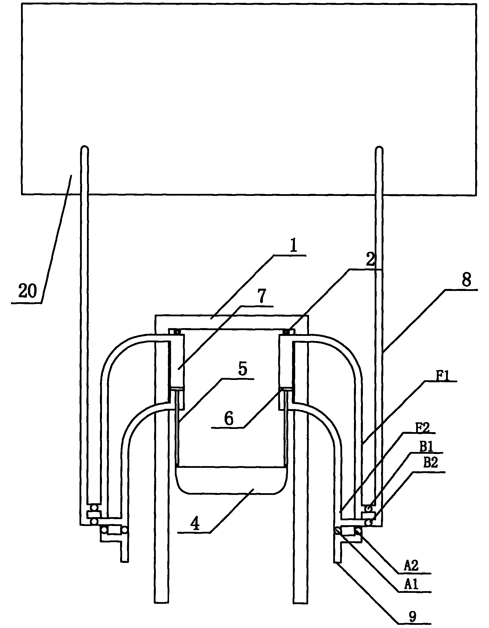
[0009] The present invention will be further described in detail below in conjunction with the accompanying drawings and embodiments.

[0010] As shown in the figure: a device that utilizes wave energy to generate electricity, including a reservoir 20, a fixed frame 1, a hydraulic device 3 is connected to the fixed frame 1 through a universal joint 2, and when the sea level rises, the floating block 4 floats up , the hydraulic rod 5 pushes the piston 6 to move upward in the hydraulic cylinder 7, and pushes the hydraulic oil to push the sea water in the first water suction pipe F1, the first water outlet pipe check valve B1 opens, and the sea water enters the water outlet pipe 8 and is sprayed from the water outlet to the storage tank. In the reservoir 20, at the same time, the lower end of the hydraulic cylinder 7 generates a strong negative pressure, the one-way valve A1 of the first water suction pipe is opened, and the seawater is sucked into the second water suction pipe F2...


PUM


Abstract

The invention discloses a power generating device by using wave energy. The device is characterized in that: a hydraulic device is axially connected with a fixed frame; one end of a hydraulic rod is provided with a piston, while the other end is axially connected with a float block; the float block is axially connected with a connecting plate; the connecting plate is axially connected with the fixed frame or a fixture on the shore; a hydraulic cylinder is connected with a suction pipe; a suction port is reserved on the suction pipe; a one-way valve is arranged on the suction pipe, and is connected with a water outlet pipe; and a one-way valve is arranged on the water outlet pipe. The power generating device has the advantages that: hydraulic oil is filled in the hydraulic cylinder, not only has certain lubricating function and reduces the friction and corrosion of the piston and the hydraulic cylinder, but also can effectively extrude sea water out of the water outlet pipe and avoid the problems of energy waste and too low pressure caused by extruding air; and the whole device can effectively increase the sea water level for hydraulic power generation by sufficiently utilizing the huge energy of sea water waves.

Description

technical field [0001] The invention relates to a device for generating electricity by utilizing wave energy. Background technique [0002] With the development of social economy, human beings' demand for energy is increasing day by day, while global oil and coal resources are decreasing day by day. In order to maintain the development and progress of human society, new energy sources must be vigorously developed. In nature, the ups and downs never stop There is a huge amount of energy hidden in the sea. Using tidal energy to generate electricity has always been the goal that people are pursuing. The power plants built in the existing tidal power generation method are easy to corrode, and at the same time cause certain damage to the marine ecological environment; for example, the patent number is 200810026612.2 A patent for a tidal wave energy power generation system. There is an inverted cylinder fixed in the sea. The mouth of the cylinder is always submerged under the sea ...

Claims


Application Information

Patent Timeline
IPC IPC(8): F03B13/16
CPCY02E10/38Y02E10/30
Inventor 陈兆红
Owner NANTONG BEICHENG SCI & TECH ENTREPRENEURIAL MANAGEMENT
Why Eureka
Try Eureka