
Method of Co-Firing Coal or Oil with a Gaseous Fuel in a Furnace

a gaseous fuel and co-fire technology, which is applied in the direction of machines/engines, lighting and heating apparatus, combustion types, etc., can solve the problem of purposely limited combustion of gaseous fuel, and achieve the effect of safe burning, easy burning, and safe combustion

Inactive Publication Date: 2015-08-13
BREEN ENERGY SOLUTIONS
View PDF2 Cites 11 Cited by
  • Summary
  • Abstract
  • Description
  • Claims
  • Application Information

AI Technical Summary

Benefits of technology

The patent describes how to safely add a gaseous fuel to a coal or oil waste furnace without interfering with the main flame. This is done by controlling the combustion of the gas with the main fuel, allowing it to improve the overall combustion process without taking away from the main flame. The method involves injecting the gas through the existing burner or separately, allowing for continued flame stability and safety. The main technical effect is improved combustion efficiency and flame stability with the use of a gaseous fuel in a coal or oil waste furnace.

Problems solved by technology

The process is that combustion of the gaseous fuel is purposefully limited in the primary flame structure of the coal or oil burner; thus maintaining original equipment flame safety and stability.

Method used


Image

  • Method of Co-Firing Coal or Oil with a Gaseous Fuel in a Furnace
  • Method of Co-Firing Coal or Oil with a Gaseous Fuel in a Furnace
  • Method of Co-Firing Coal or Oil with a Gaseous Fuel in a Furnace

Examples


Embodiment Construction

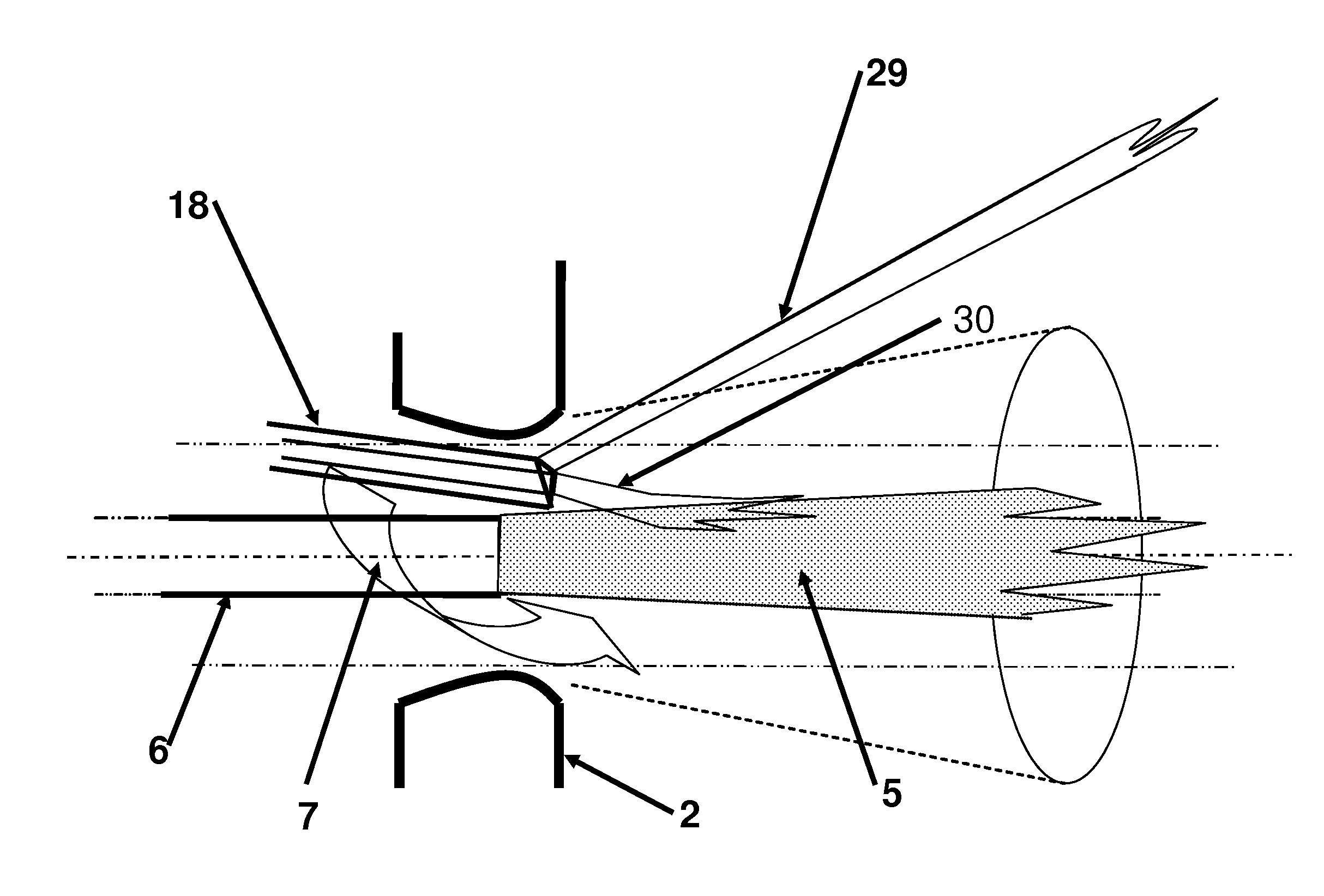
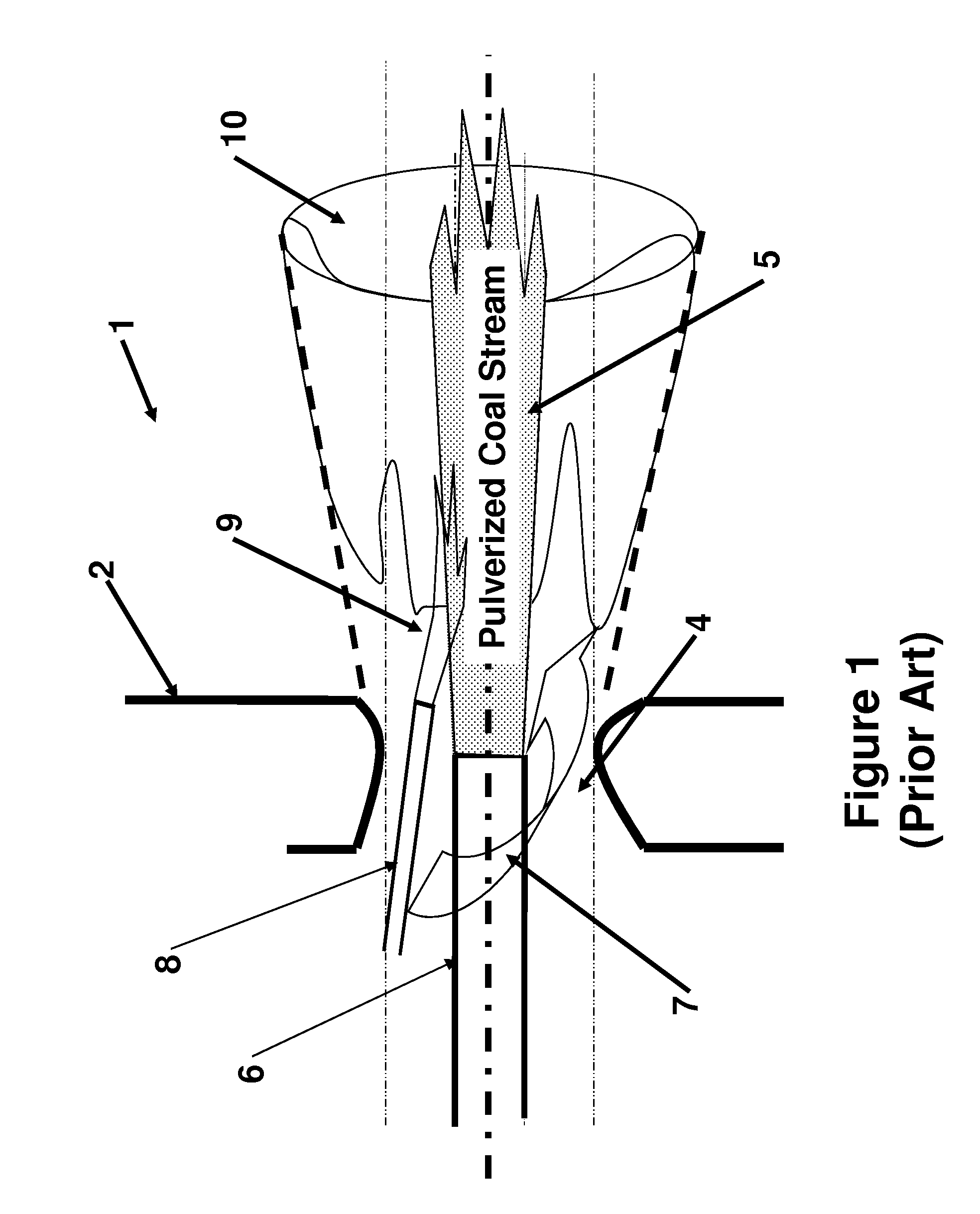
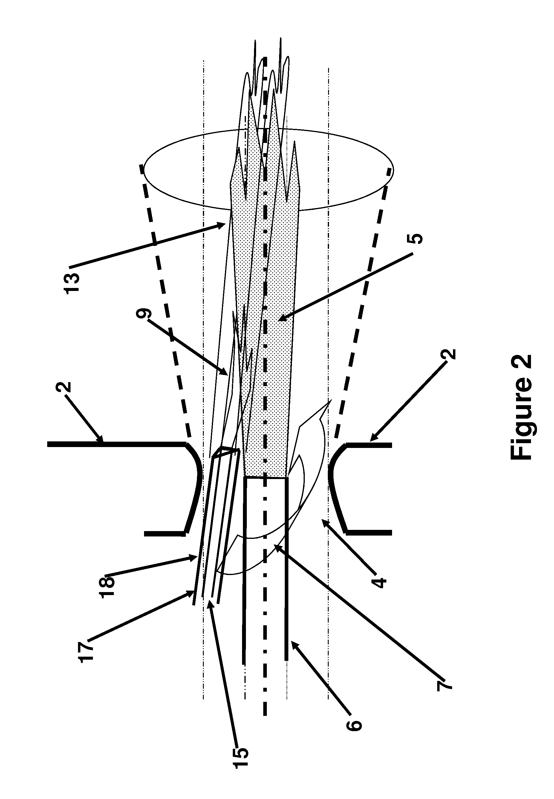
[0029]A typical coal fired boiler has several burners into which pulverized coal in a stream of air is injected into a flame zone. Natural gas, i.e. methane, is separately injected into the burner. The gas injection may be accomplished through gas igniter tubes, or through separate higher velocity injector piping tips, spuds or nozzles. Normal igniter operation is shown in FIG. 1, where the igniter establishes its own stable flame structure, which then impinges on the main condensed phase fuel stream as it heats-up and mixes with its dedicated burner air supply. As can be seen in FIG. 1, a typical swirl type burner 1 is provided on the wall 2 of a boiler. The burner 1 has an opening 4 in which there is an injector tube 6 through which a stream of pulverized coal 5 is injected. Swirling combustion air 7 is injected through the opening 4 around the injector tube 6. Typically the combustion air is injected at a different velocity than the pulverized coal. An igniter tube 8 is positione...


PUM


Abstract

Methods for co-firing a fuel containing coal or oil that is injected into a burner in a furnace by injecting a gaseous fuel are disclosed. The gaseous fuel is injected in a manner so as not to consume air that would otherwise combine with the coal or oil in the primary flame. This can be accomplished by injecting the gaseous fuel at a higher or lower velocity than the coal or oil and combustion air are being injected. This can also be accomplished by directing the gaseous fuel being injected away from the primary flame created when the coal or oil burns.

Description

CROSS-REFERENCE TO RELATED APPLICATION[0001]This application claims the benefit of provisional application Ser. No. 61 / 938,934 filed Feb. 12, 2014.FIELD OF INVENTION[0002]The present invention is directed toward controlling the operation of a furnace and in which coal or oil is burned in combination with a gaseous fuel.BACKGROUND OF THE INVENTION[0003]Coal and oil fired boilers are used to generate steam for many industrial purposes, chief among which is to drive electric generating, steam powered turbines for the electric utility industry. The coal or oil occur in a condensed solid or liquid state and must be ground or pulverized, in the case of coal, or atomized, in the case of oil, before being able to be combusted efficiently in the furnace section of the boiler.[0004]Either of these finely ground or atomized, but still condensed phase, fuels then must be heated to an extent so as to volatilize a portion of the fuel into the gaseous phase before mixing with air and combustion be...

Claims


Application Information

Patent Timeline
Patent Type & Authority Applications(United States)
IPC IPC(8): F23C1/04F23N1/00F23D17/00F23C1/08F23C1/10
CPCF23C1/04F23C1/08F23C1/10F23C2900/07021F23N1/005F23N2027/02F23N2025/00F23D17/00F23N5/003F23C1/12F23D17/002F23D17/005F23C2201/301F01K5/02F23N2225/00F23N2227/02
Inventor CHOTHANI, CHETANLOCKERT, CHARLESBREEN, BERNARD P.DEPAOLI, ALAN
Owner BREEN ENERGY SOLUTIONS
Learn More