
Apparatus and method for controlling transmission power in a wireless communication system

a wireless communication system and apparatus technology, applied in the field of apparatus and method for controlling transmission power, can solve the problems of signal retransmission, power consumption increase, and increase in transmission power in the terminal,

Active Publication Date: 2010-10-26
SAMSUNG ELECTRONICS CO LTD +1
View PDF6 Cites 25 Cited by
  • Summary
  • Abstract
  • Description
  • Claims
  • Application Information

AI Technical Summary

Benefits of technology

The present invention provides an apparatus and method for controlling the transmission power of a terminal in a wireless communication system to minimize power consumption, resource use, and collisions. The method involves transmitting a header field containing information related to a transmission rate and length of data transmitted in a frame to a receiving terminal at a maximum transmit power level available to the transmitting terminal. The receiving terminal then determines the transmission duration of the data based on the transmission rate and length information in the header field, and discontinues transmission of a new frame during that duration. This allows for efficient use of resources and reduces power consumption in the wireless communication system.

Problems solved by technology

Although the terminals transmission signals with optimum transmit power, thus avoiding collision, an increase in the transmission power increases power consumption in the terminals in the IEEE 802.11a WLAN communication system.
The resulting collision leads to a signal retransmission.
Eventually, power consumption is increased.

Method used


Image

  • Apparatus and method for controlling transmission power in a wireless communication system
  • Apparatus and method for controlling transmission power in a wireless communication system
  • Apparatus and method for controlling transmission power in a wireless communication system

Examples


Embodiment Construction

[0049]A preferred embodiment of the present invention will be described herein below with reference to the accompanying drawings. In the following description, well-known functions or constructions are not described in detail since they would obscure the invention in unnecessary detail.

[0050]The present invention provides a method of minimizing the transmission power consumption of a terminal in a wireless communication system, especially in a WLAN. The present invention also provides a method of minimizing the transmission power of the terminal without using additional resources and creating a transmission delay by supporting the interworking between a MAC layer and a PHY layer in the WLAN communication system. The following description is made in the context of the WLAN model based on the IEEE 802.11a standard, by way of example.

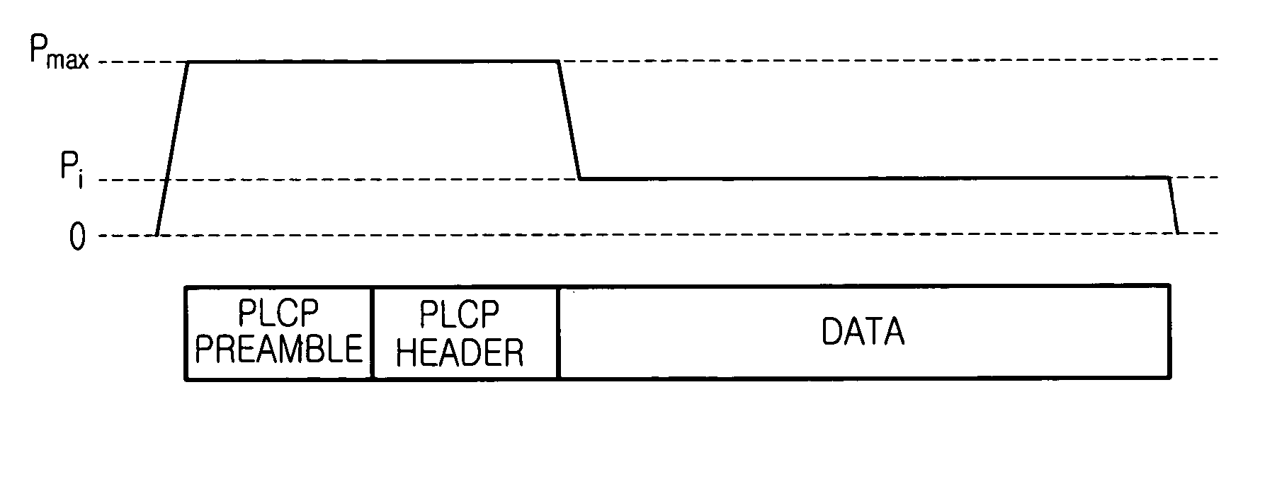
[0051]With reference to FIG. 5, the format of a PLCP PDU (or PPDU) for the IEEE 802.11a WLAN communication system will be described.

[0052]FIG. 5 is a diag...


PUM


Abstract

A method and system for controlling the transmission power of a terminal transmitting frames in a wireless communication system, the frames having a frame structure including a header field containing information related to a transmission rate and length of data transmitted in a frame and a data field having the data. The transmitting terminal transmits the header field to a receiving terminal at a maximum transmit power level available to the transmitting terminal so that second terminals other than the transmitting terminal and the receiving terminal within the wireless communication system can identify that resources are in use. The transmitting terminal transmits the data field at an optimum transmit power level great enough to allow the data field to reach the receiving terminal.

Description

PRIORITY[0001]This application claims priority under 35 U.S.C. §119 to an application entitled “Apparatus and Method for Controlling Transmit Power in a Wireless Communication System” filed in the Korean Intellectual Property Office on Oct. 27, 2003 and assigned Serial No. 2003-75195, the contents of which are incorporated herein by reference.BACKGROUND OF THE INVENTION[0002]1. Field of the Invention[0003]The present invention relates generally to a wireless communication system, and in particular, to an apparatus and method for controlling transmission power, which minimizes power consumption in a terminal.[0004]2. Description of the Related Art[0005]A major wireless communication system, WLAN (Wireless Local Access Network) provides services as available in an existing wired LAN system using a wireless medium as a data transmission medium. The WLAN system can transmit and receive data using minimum circuit connections by utilizing RF (Radio Frequency) technology. Diverse WLAN syst...

Claims


Application Information

Patent Timeline
Patent Type & Authority Patents(United States)
IPC IPC(8): G08C17/00H04B7/005H04B7/26
CPCH04W52/286H04W52/367H04W52/50H04B7/26H04W52/26
Inventor KIM, YOUNG-SOOCHOI, SUNG-HYUNJANG, KYUNG-HUNHWANG, HYO-SUN
Owner SAMSUNG ELECTRONICS CO LTD
Learn More