
System and method for building large-scale layer 2 computer networks

Active Publication Date: 2010-10-26
CISCO TECH INC
View PDF29 Cites 37 Cited by
  • Summary
  • Abstract
  • Description
  • Claims
  • Application Information

AI Technical Summary

Benefits of technology

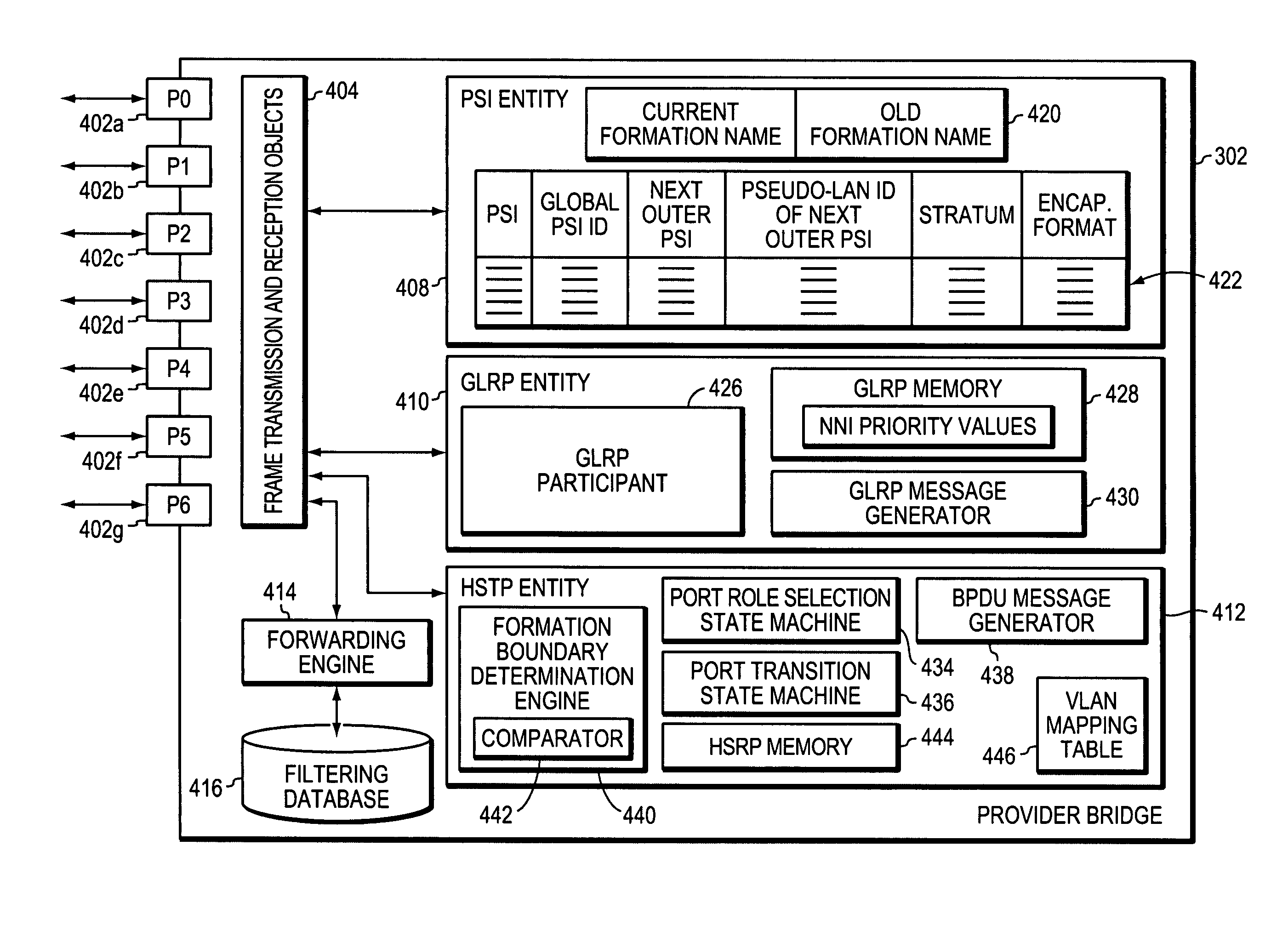
[0041]The present invention further includes a novel extension to the Generic Attribute Registration Protocol (GARP), which is referred to as the GARP L2-NNI Registration Protocol (GLRP). Essentially, GLRP blocks redundant links extending between different formations of the grand network that might otherwise create loops. Basically, by executing GLRP, the Provider Bridges determine whether a given NNI is blocked or forwarding for any given S-VLAN. In this way, loops between the formations are prevented. More specifically, the Provider Bridges within a formation identity all NNIs. Those NNIs that lead from the current formation to a higher level formation are referred to as lower NNIs. For each PSI / lower NNI pair within a given formation, the Provider Bridges, by executing GLRP, select only a single lower NNI for forwarding frames for that PSI. All other lower NNIs within the formation are blocked for that PSI. In this way, loops, which might otherwise exist due to the use of redundant NNI links between the formations are blocked.

Problems solved by technology

Both 10Base-T and 100Base-T, however, are limited to cable lengths that are less than 100 meters.
Gigabit Ethernet thus represents a potentially significant increase in the size or range of Ethernet LANs.
The existence of redundant links, however, may cause the formation of circuitous paths or “loops” within the network.
Loops are highly undesirable because data frames may traverse the loops indefinitely.
Furthermore, some devices, such as bridges or switches, replicate frames whose destination is not known resulting in a proliferation of data frames along loops.
The resulting traffic can overwhelm the network.
The need to convert each network message from Ethernet to ATM and back again requires the WAN or MAN to include expensive networking equipment.
As a result, WANs and MANs can be expensive to build and operate.

Method used


Image

  • System and method for building large-scale layer 2 computer networks
  • System and method for building large-scale layer 2 computer networks
  • System and method for building large-scale layer 2 computer networks

Examples


Embodiment Construction

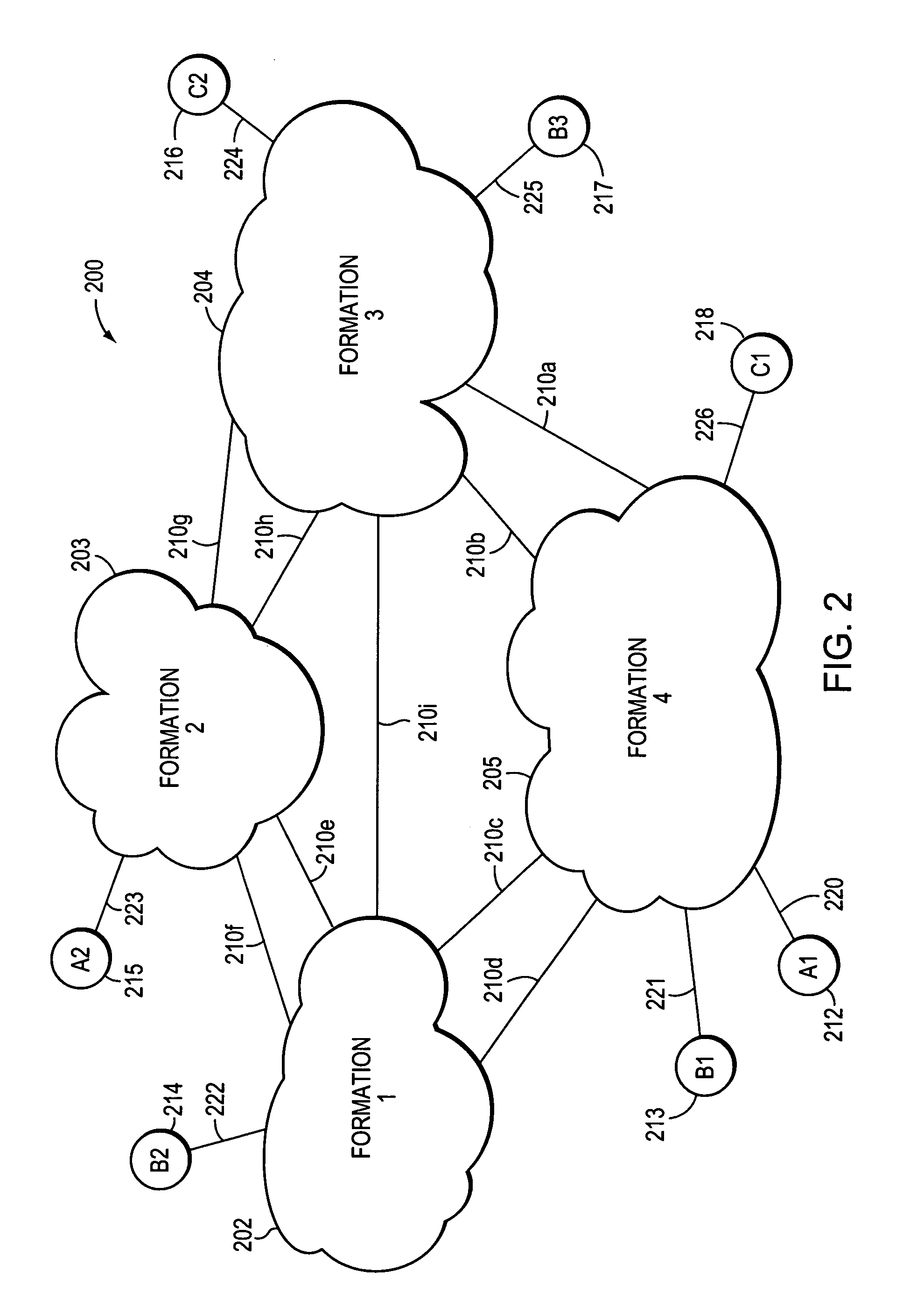
[0050]FIG. 2 is a highly schematic illustration of a large-scale, e.g., “grand”, layer 2 (L2) computer network 200 in accordance with the present invention. The grand network may span a region such as Europe, or an entire continent, such as North America. Grand network 200 is made up of a plurality of formations, such as formations 202-205, which are also identified as formations 1-4. Each formation 202-205 includes a plurality of interconnected Layer 2 (L2) intermediate network devices, such as Provider Bridges. In accordance with the preferred embodiment, each Provider Bridge conforms to the IEEE P802.1ad “Standard for Local and Metropolitan Area Networks—Virtual Bridged Local Area Networks—Amendment 4: Provider Bridges”, the most current version of which is Draft 3.0, Oct. 25, 2004, which is hereby incorporated by reference in its entirety. Typically, each formation is operated by the same administrative entity, and therefore represents a separate administrative domain. Some or a...


PUM


Abstract

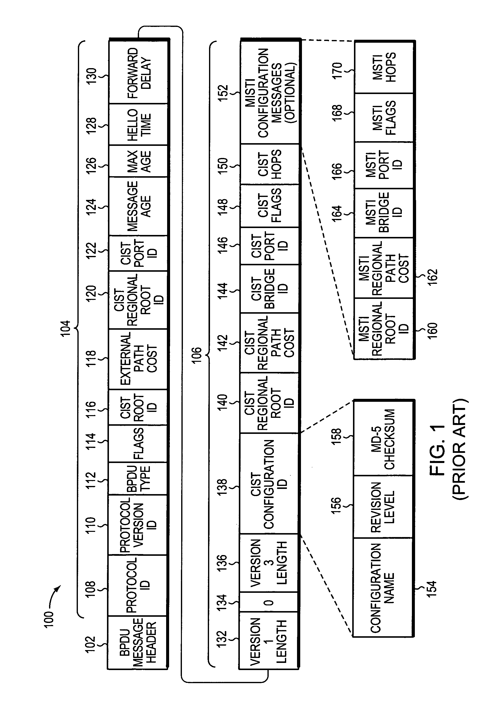
A grand computer network is formed from layer 2 (L2) networking technology in which groups of Provider L2 bridges are organized into formations, and different formations are interconnected via network-network interface (NNI) links. Customer sites are coupled to the formations. Customers identify their traffic, e.g., frames, by labeling or tagging it with a Customer Virtual Local Area Network (VLAN) Identifier (C-VLAN ID) or Customer Service Instance (CSI). Within the formations, the C-VLAN ID is mapped to a Service VLAN ID (S-VLAN ID) or Provider Service Instance (PSI), and the S-VLAN ID is appended to the customer traffic. The PSIs are hierarchical, such that each PSI belongs to at most one other “outer” or higher-level PSI, but may itself own any number of “inner” or lower-level PSIs. As a given frame traverses through the different formations of the Grand Network via the NNI links, the frame acquires an encapsulation, sheds an encapsulation or exchanges its current encapsulation for a different one. Bridges within the formations run a Hierarchical Spanning Tree Program (HSTP) to block intra-formation loops, and a GARP L2-NNI Registration Protocol (GLRP) to block inter-formation loops.

Description

CROSS-REFERENCE TO RELATED APPLICATIONS[0001]This invention is cross-related to the following co-pending application, which is hereby incorporated by reference in its entirety:[0002]U.S. patent application Ser. No. 10 / 279,360, filed Oct. 24, 2002 for a LARGE-SCALE LAYER 2 METROPOLITAN AREA NETWORK, and published as Publication Number US 2004-0081171 A1 on Apr. 29, 2004, now issued as U.S. Pat. No. 7,292,581.BACKGROUND OF THE INVENTION[0003]1. Field of the Invention[0004]This invention relates to computer networks and, more specifically, to large-scale networks.[0005]2. Background Information[0006]Many organizations, including businesses, governments and educational institutions, utilize computer networks so that employees and others may share and exchange information and / or resources. A computer network typically comprises a plurality of entities interconnected by means of one or more communications media. An entity may consist of any device, such as a computer, that “sources” (i.e....

Claims


Application Information

Patent Timeline
IPC IPC(8): H04L12/28H04L12/56G06F15/16
CPCH04L45/00H04L45/18H04L45/48H04L12/4641H04L45/76
Inventor FINN, NORMAN W.ELANGOVAN, ANUSANKAR
Owner CISCO TECH INC
Learn More