
Method for manufacturing squirrel cage rotor

a technology of cage rotors and cages, which is applied in the direction of rotors, synchronous motors,foundry moulding apparatus, etc., can solve the problems of high cost, no prior art insulation system provides ideal insulation for high efficiency, and neither enables effective consumable pattern casting of conductors with copper, so as to eliminate its organic content

Inactive Publication Date: 2005-06-23
SWEO EDWIN A
View PDF22 Cites 36 Cited by
  • Summary
  • Abstract
  • Description
  • Claims
  • Application Information

AI Technical Summary

Benefits of technology

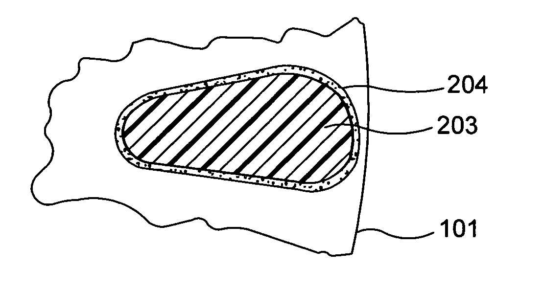
[0012] Squirrel cage rotor conductors, including end rings 202 and slot conductors 203, may be cast using standard casting techniques, such as die casting or consumable pattern casting, employing slots lined with ceramic adhesive 204 as part of the mold for the conductors. If desired, only a majority of the slots may include a cast conductor, e.g., by plugging the slots that are to remain free of the conductor before the casting process is carried out. The ceramic insulation provides thermal insulation between the molten metal and the lamination stack 101 during casting, enabling longer bars to be cast through the lamination stack than with other insulation methods, and then serves as an electrical insulator to prevent leakage currents from circulating in the laminations of the rotor during operation. This approach enables consumable pattern casting with copper, for reduced rotor losses, even though copper casting may be done at temperature approaching or even exceeding 2500° F.
[0014] The conductive bars used in the slots of brushless doubly-fed rotors, such as those described in U.S. Pat. No. 5,239,251, and in U.S. Pat No. 6,278,211 (the drawings and specification of which are hereby specifically incorporated herein by reference), can be also be insulated from the laminations with this ceramic adhesive insulation method, to avoid the substantial parasitic torques that arise as a result of conventional die casting or non-insulated / poorly insulated inserted bar construction. The interconnection conductors between bars for these rotors can be cast simultaneously with the bars, using the consumable pattern casting technique, and employing copper for the conductors, to achieve reduced rotor losses.
[0016] The ceramic insulating coating comprises a binder and a ceramic powder, and the ceramic powder preferably includes at least one of an alumina, a berylia, a magnesia, a thoria, a zirconia, a zircon, a spinel, and a mullite powder. Most preferably the ceramic powder comprises an alumina powder. The binder of the ceramic insulating coating can comprise either an inorganic binder, or an organic-based material that is processed after the slots are lined (e.g., by heating) to substantially eliminate its organic content.

Problems solved by technology

However, none of these prior art insulation systems provides ideal insulation for high efficiency and minimum unbalanced pull, and none enables an effective consumable pattern casting of the conductors with copper.
Other prior art insulating systems for fabricated rotors either employ slot liners or use an insulating film that is applied to conductive bars that are then inserted into the slots; however, both of these approaches are expensive.
The higher temperature used for making die-cast rotor conductor assemblies of copper places too much thermal stress on portions of the dies, resulting in very short die life.
Indeed, even if cast from aluminum or other lower-temperature metal, the rotor conductor assemblies can place too much thermal stress on the conventional oxide coatings used for insulation and thereby cause electrical leakage currents.

Method used


Image

  • Method for manufacturing squirrel cage rotor
  • Method for manufacturing squirrel cage rotor
  • Method for manufacturing squirrel cage rotor

Examples


Embodiment Construction

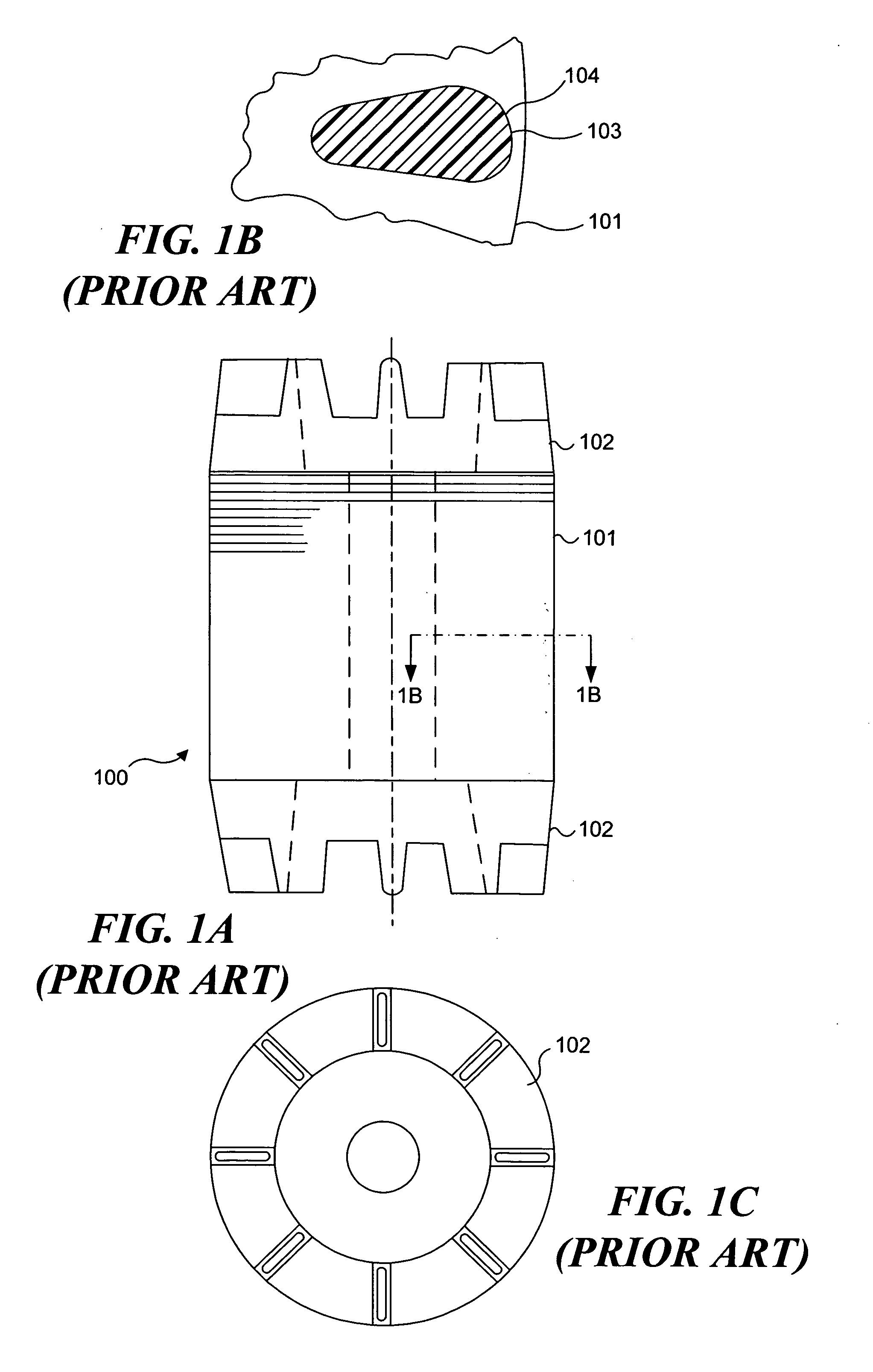
[0035] A preferred embodiment of a conventional singly-fed induction machine squirrel cage rotor 200 with ceramic adhesive insulated slots, in accord with the present invention, is shown in FIGS. 3A, 3B, and 3C. Ceramic adhesive coating 204, which is applied on the inside surface of the closed slots in lamination stack 101, thermally and electrically insulates cast slot conductors 203 from the lamination stack. End rings 202 electrically connect all conductors 203 at each end of the rotor. Coating 204 provides substantial thermal insulation of the molten metal from the large mass of the steel lamination stack during the brief (about one second) casting period, but does not substantially reduce the transfer of heat from conductors 203 to the lamination stack during subsequent operation of the induction machine. Rotor 200 is generally identical to a conventional squirrel cage rotor, like that shown in prior art views of FIGS. 1A, 1B, and 1C, except that it includes ceramic adhesive co...


PUM

PropertyMeasurementUnit
Temperatureaaaaaaaaaa
Electrical conductivityaaaaaaaaaa
Electrical conductoraaaaaaaaaa

Abstract

Ceramic adhesive is applied inside the slots of an electric machine squirrel cage rotor prior to casting or insertion of rotor conductors. This heat-resistant insulation provides superior electrical insulation that is also mechanically rugged, thus enabling casting of squirrel cage rotors by die or cost-effective consumable pattern casting. The consumable pattern cast copper rotors are electrically well insulated, thus minimizing rotor losses. The ceramic insulation in cast rotors enables longer conductors to be cast by thermally insulating the molten metal from the cooler laminations. The ceramic insulation in fabricated rotors withstands the high temperatures of end ring attachment. This method is applicable to both conventional induction machine rotors and brushless doubly-fed induction machine rotors and provides the degree of electrical isolation of the bars from the laminations needed to avoid excessive parasitic torques in doubly-fed machines, while ensuring adequate thermal conductivity to dissipate conductive bar heat to the laminations.

Description

RELATED APPLICATIONS [0001] This application is based on a prior copending provisional application, Ser. No. 60 / 530,218, filed on Dec. 17, 2003, the benefit of the filing date of which is hereby claimed under 35 U.S.C. § 119(e).FIELD OF THE INVENTION [0002] The present invention generally pertains to squirrel cage rotors of electrical induction machines, including both conventional singly-fed induction machine rotors and brushless doubly-fed rotors, and more specifically, pertains to the use of a ceramic adhesive insulation that is applied on the interior surface of the slots during the manufacture of such rotors, prior to either the casting or insertion of rotor conductors within the slots. BACKGROUND OF THE INVENTION [0003] The rotor slot conductors of squirrel cage rotor electric machines must be electrically insulated from the steel lamination stack of the rotor to prevent stray electrical currents from leaking into the lamination stack. Such currents cause loss of efficiency an...

Claims


Application Information

Patent Timeline
IPC IPC(8): B22C9/04B22D19/00H02K15/00H02K15/02H02K17/16
CPCB22C9/04B22D19/0054Y10T29/49009H02K17/165Y10T29/49012H02K15/0012H02K17/20
Inventor SWEO, EDWIN A.
Owner SWEO EDWIN A
Learn More