Eureka AIR delivers breakthrough ideas for toughest innovation challenges, trusted by R&D personnel around the world.

Correlated magnetic belt and method for using the correlated magnetic belt

a technology of correlated magnetic belts and belts, applied in the field of belts, can solve the problems of requiring a great degree of dexterity on the part of the user

Inactive Publication Date: 2010-10-19
CORRELATED MAGNETICS RES LLC
View PDF49 Cites 75 Cited by
  • Summary
  • Abstract
  • Description
  • Claims
  • Application Information

AI Technical Summary

Benefits of technology

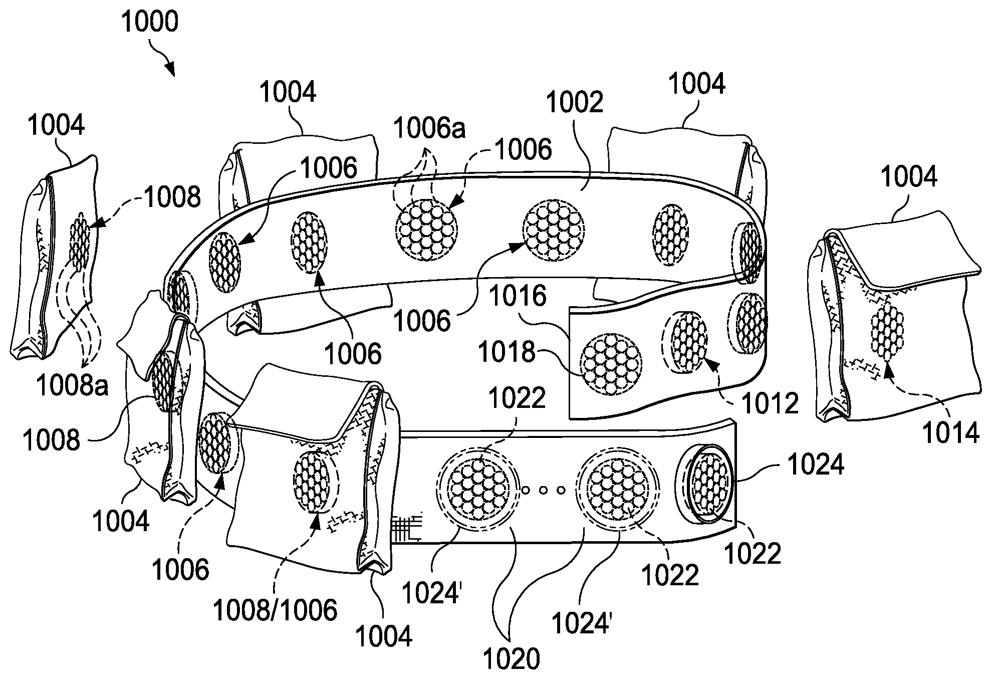
"The present invention provides a belt that can securely hold and release objects using a field emission structure. The belt has a strap with a first field emission structure that interacts with a second field emission structure associated with the object. The object is attached to the strap when the first and second field emission structures are aligned with each other. The first and second field emission structures have a desired spatial force function that creates a spatial force in response to their relative alignment. The field domain is the area where the first and second field emissions interact. The method involves attaching the first field emission structure to the belt, attaching the second field emission structure to the object, and aligning the first and second field emission structures so the object attaches to the belt when the first and second field emission structures are located next to each other. The object can be easily released from the belt by turning the first and second field emission structures. The invention provides a strap with one end attached to the other end when the first and second field emission structures are located next to each other and have a certain alignment with respect to each other. The one end can be separated from the other end when the first and second field emission structures are turned with respect to each other."

Problems solved by technology

Unfortunately, the traditional scuba weight belt employs loops, buckles, clamps, hooks, or other known fastening mechanisms which require a great degree of dexterity on the part of the person to use when they secure objects thereto and remove objects therefrom.

Method used


Image

  • Correlated magnetic belt and method for using the correlated magnetic belt
  • Correlated magnetic belt and method for using the correlated magnetic belt
  • Correlated magnetic belt and method for using the correlated magnetic belt

Examples


Embodiment Construction

[0014]The present invention includes a belt which utilizes correlated magnetic technology to enable a wide variety of objects (e.g., tools, flashlights, cameras, weight pouches) to be easily connected thereto and removed therefrom. The belt which utilizes correlated magnetic technology is a significant, improvement, over a conventional belt which employs loops, buckles, clamps, hooks, or other known fastening devices to enable the connection and removal of objects (e.g., tools, flashlights, cameras). This significant improvement over the state-of-art is attributable, in part, to the use of an emerging, revolutionary technology that is called correlated magnetics.

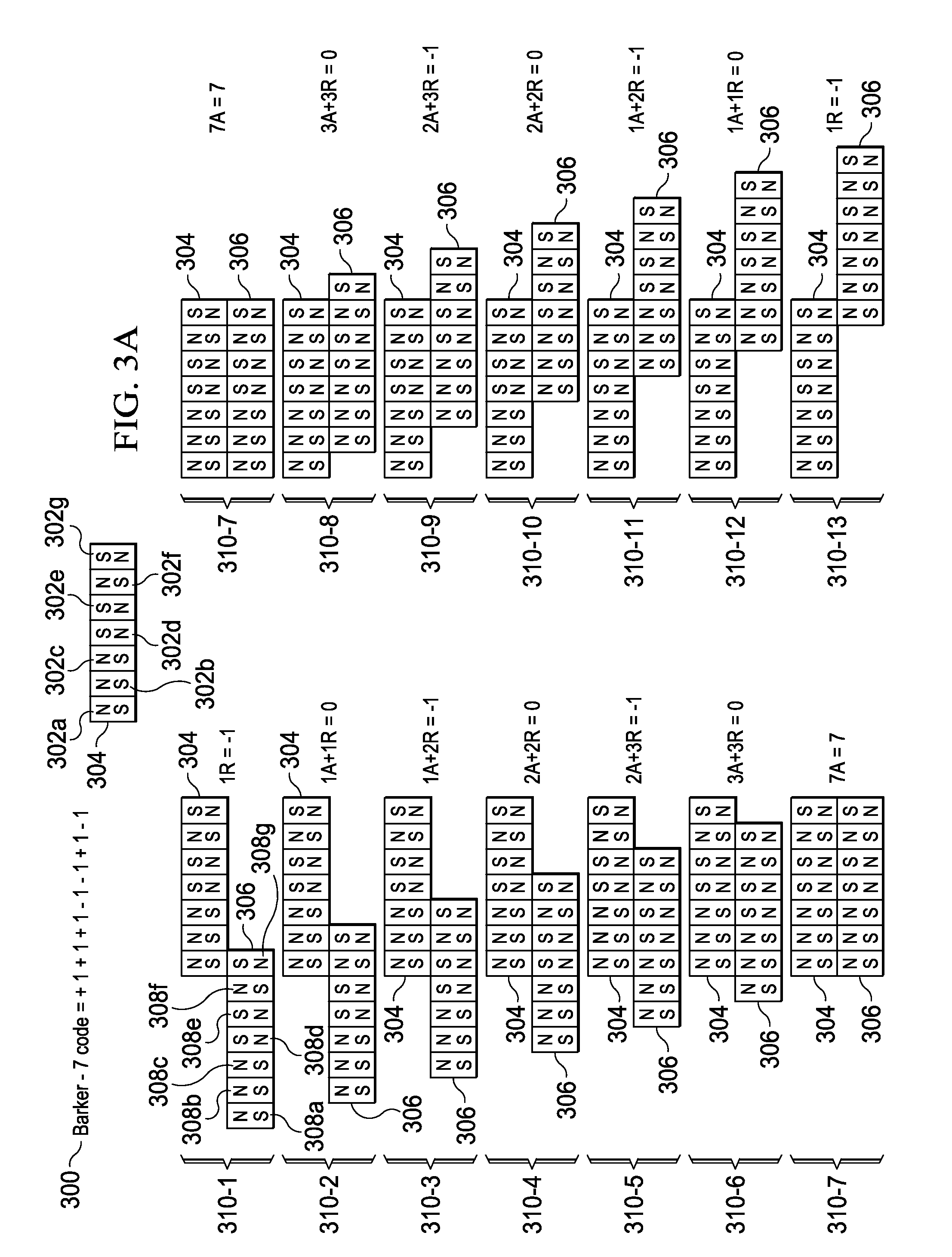
[0015]This new revolutionary technology called correlated magnetics was first fully described and enabled in the co-assigned U.S. patent application Ser. No. 12 / 123,718 filed on May 20, 2008 and entitled “A Field Emission System and Method”. The contents of this document are hereby incorporated herein by reference. A second ...


PUM

PropertyMeasurementUnit
magnetic fieldaaaaaaaaaa
spatial forceaaaaaaaaaa
forceaaaaaaaaaa

Abstract

A belt is described herein that uses correlated magnets to enable objects to be secured thereto and removed therefrom. Some examples of such a belt include a construction work belt, a soldier belt, an astronaut belt a home handyman belt, a plumber's belt, an electrician's belt, a telephone repairman's belt, a lineman's belt, a fisherman's belt, a hunter's belt, a sports belt, and a scuba weight belt. For instance, the scuba weigh belt can have different types of objects secured thereto and removed therefrom such as a weight pouch, a utility pocket, a dive light (flash light), a camera, a scuba lanyard, a navigation board, a depth gauge, a spear gun, or any type of military equipment.

Description

CROSS REFERENCE TO RELATED APPLICATIONS[0001]This application is a continuation-in-part application of U.S. patent application Ser. No. 12 / 476,952 filed on Jun. 2, 2009 and entitled “A Field Emission System and Method”, which is a continuation-in-part application of U.S. patent application Ser. No. 12 / 322,561 filed on Feb. 4, 2009 and entitled “A System and Method for Producing an Electric Pulse”, which is a continuation-in-part application of U.S. patent application Ser. No. 12 / 358,423 filed on Jan. 23, 2009 and entitled “A Field Emission System and Method”, which is a continuation-in-part application of U.S. patent application Ser. No. 12 / 123,718 filed on May 20, 2008 and entitled “A Field Emission System and Method”. The contents of these four documents are hereby incorporated herein by reference.TECHNICAL FIELD[0002]The present invention is related to a belt that incorporates correlated magnets which enable objects to be secured to and removed from the belt. Some examples of suc...

Claims


Application Information

Patent Timeline
Patent Type & Authority Patents(United States)
IPC IPC(8): A41F9/00A41F3/02H01F7/02H01F7/20
CPCA45F5/02A45F5/021A45F2003/144A45F2200/0575A45F2200/0591H01F7/0215H01F7/0263
Inventor FULLERTON, LARRY W.ROBERTS, MARK D.
Owner CORRELATED MAGNETICS RES LLC
Why Eureka
Eureka Blog
Learn More