
Hunting bullet with reduced aerodynamic resistance

a technology of aerodynamic resistance and bullets, which is applied in the direction of ammunition, ammunition projectiles, weapons components, etc., can solve the problems of large loss of mass on impact with the target, high velocity loss on the trajectory, and impair the terminal efficiency, so as to reduce the aerodynamic drag coefficient and reduce the aerodynamic drag on the trajectory. , the effect of low aerodynamic drag

Active Publication Date: 2010-10-19
SAUVESTRE JEAN CLAUDE
View PDF24 Cites 12 Cited by
  • Summary
  • Abstract
  • Description
  • Claims
  • Application Information

AI Technical Summary

Benefits of technology

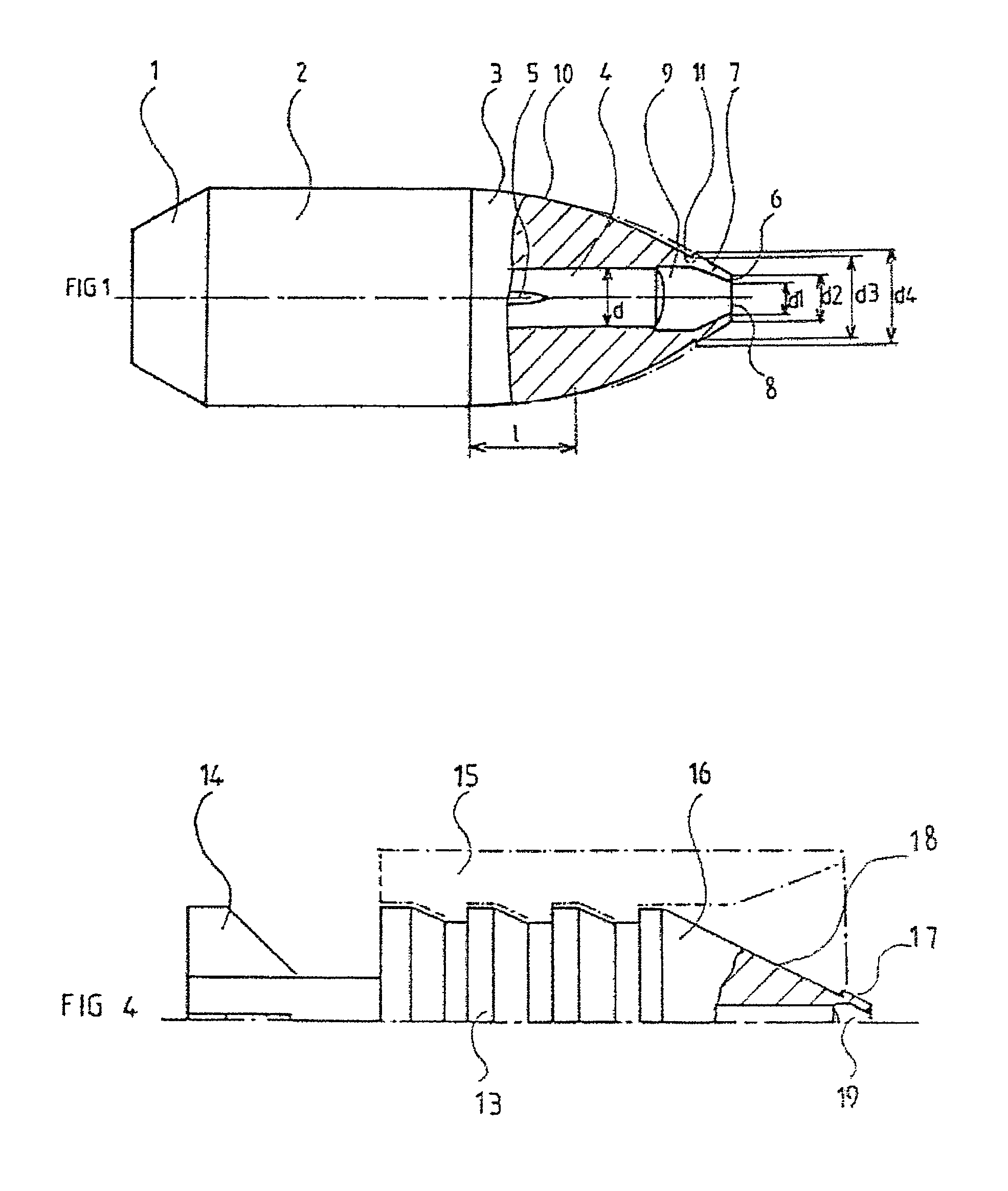
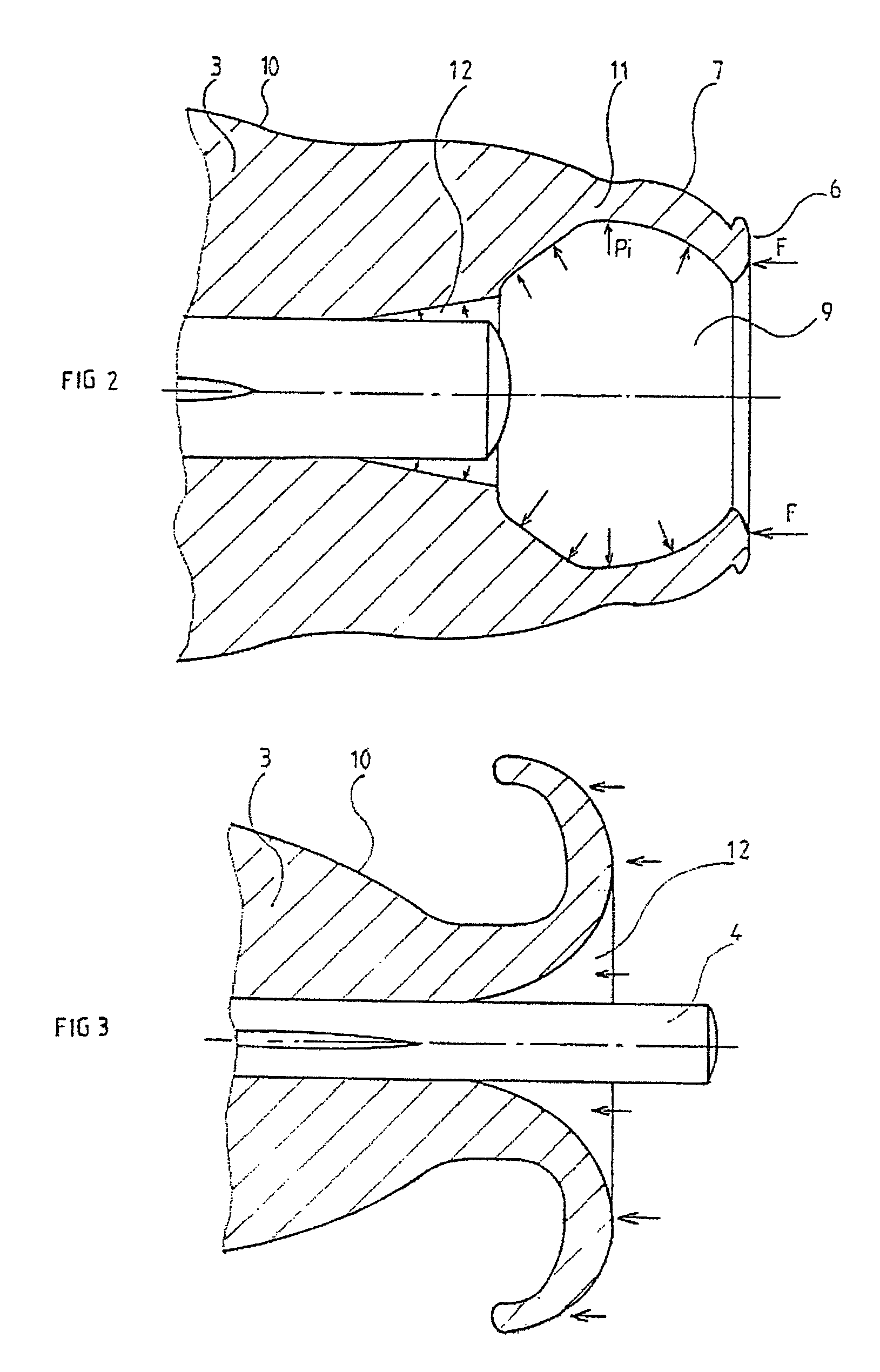
[0015]The deformation notches made in the wall of the ogival head are intended to make it easier for the nose of the ogive to deform and open on impact with the target, in order to cause a deformation by “mushrooming”.
[0016]These deformation notches contribute to the stepped ogival shape of the front portion of the bullet. This ogival shape comprises an ogival nose surrounding the orifice communicating with the conical or cylindro-conical cavity, and a rear portion, which interact to minimize and reduce as much as possible any discontinuity of air flow in flight which could cause Mach wave detachments impairing the aerodynamic drag.
[0021]According to another advantageous embodiment, the front of the internal shaft protrudes slightly into the internal cavity formed in the ogival nose, that is to say that the truncated cone-shaped or cylindrical wall of the base of the internal cavity comes into contact with the external surface of the shaft slightly behind the front end of the latter. This has the effect of forming an annular volume that may serve as an expansion notch of the bullet head on impact with the target.
[0023]The bullet according to the present invention has the advantage of substantially reducing the aerodynamic drag on the trajectory, while ensuring control of the deformation of the body of the bullet on impact with the target, even at great distance. Thus, by comparison with a bullet according to patent FR-A-2.795.170 having the same mass and the same dimensions, the coefficient of aerodynamic drag is reduced by approximately half for projectile velocities of the order of Mach 2.
[0024]More particularly, the low aerodynamic drag on the trajectory allows the bullet of the invention to retain a high velocity until impact with a target more than 300 m away. Thus, the bullet then deforms in a controlled manner by rolling up about its axis, on impact with the soft portions of the target, and ensures the effective destruction of the hard portions of said target, even at great distances, which may be greater than 300 m in the case of bullets of the caliber.
[0025]This result may be obtained, according to the invention, with a metal lead-free bullet, although the volumic mass of the materials usually used as lead substitutes is approximately 20% less than the latter, and the volume of the bullet is substantially identical because of the standards imposed in this technical field. It is known that the highest possible bullet mass is necessary, for a given caliber and a determined aerodynamic drag coefficient, to obtain sufficient energy on impact. The invention therefore makes it possible to offset the consequences of the reduction in the volumic mass of lead-free bullets, and to improve the terminal efficiency of the bullet.

Problems solved by technology

This ammunition usually has the disadvantage of a high velocity loss on the trajectory and a major loss of mass on impact with the target due to a break-up of the bullet.
However, these bullets fragment and expand poorly on impact with the target, which impairs their terminal efficiency.
This technique has the disadvantage of a random expansion, and a risk of fragmentation of the petals formed.
In addition, the method of manufacture of this type of bullet by cold stamping causes dynamic imbalances which have the effect of a dispersion of the shots.
According to this technique, the diameter of the nose of the ogive represents approximately between 40 and 50% of the maximum diameter of the bullet, which provides it with considerable aerodynamic drag.

Method used


Image

  • Hunting bullet with reduced aerodynamic resistance
  • Hunting bullet with reduced aerodynamic resistance
  • Hunting bullet with reduced aerodynamic resistance

Examples


Embodiment Construction

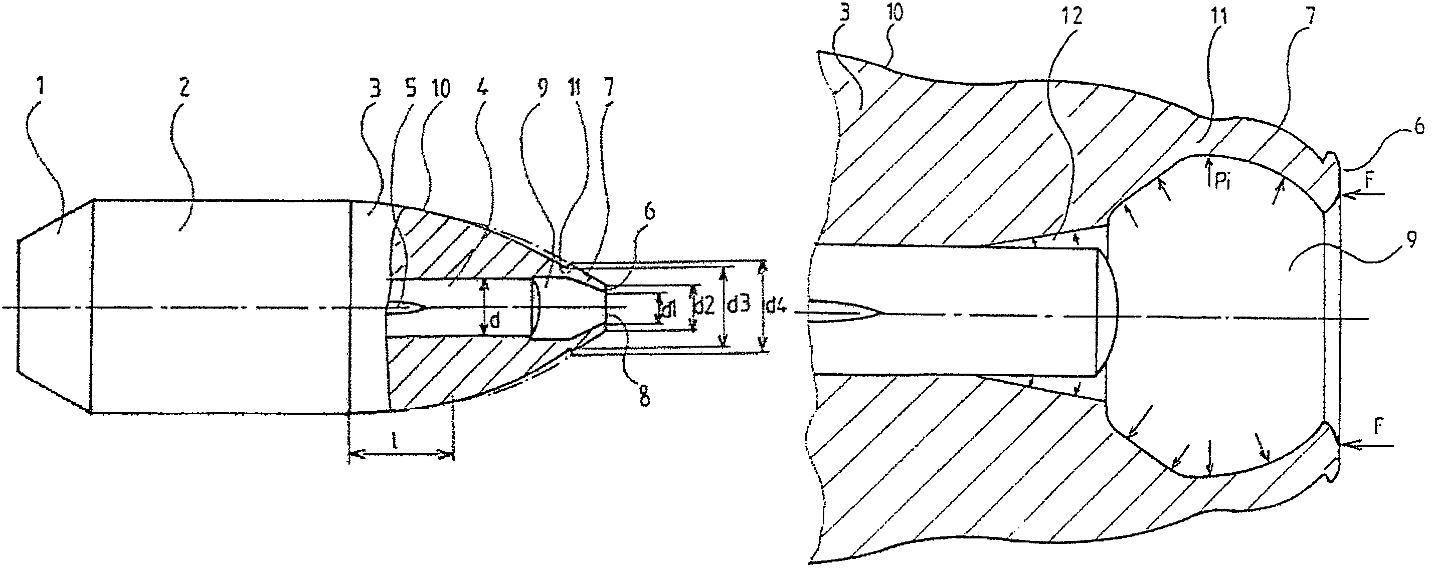
[0038]As shown in FIG. 1, the bullet with the caliber of the gun is of the monobloc metal type and comprises at its rear portion a basal narrowing (1), at its central portion a body (2), and at its front portion a stepped ogive (3).

[0039]An internal supported shaft (4) whose surface supports longitudinal ribs (5) is placed in a hole drilled in the axis of the bullet body and passing through the ogive (3).

[0040]The bullet supporting the internal shaft (4) is inserted into a case furnished with a percussion cap and a charge, of conventional type, not shown.

[0041]The ogival head (3) of the bullet is very streamlined to reduce aerodynamic drag as much as possible, and the diameters d1 of the orifice (8) and d2 of the flat (6) of the nose (7) that surrounds it are as small as possible. Thus, in the example of FIG. 1, the diameter d2 of the flat is slightly less than the diameter d of the internal shaft (4), the ratio d2:d being close to 0.8:1, while the diameter d1 of the orifice is such...


PUM


Abstract

The invention relates to ammunition for hunting guns.The bullet is of the type comprising an internal shaft (4) with a rigidity equal to or greater than that of the body of the bullet, disposed in a hole drilled in the body of the bullet along its axis, and this internal shaft (4) is set back from the orifice (8) of the hole, the latter, situated on the axis, has a smaller diameter than that of the internal shaft (4), and the wall of the ogival head (3) of the bullet body (2) comprises one or more deformation notches close to the orifice of the hole.Applicable to the improvement of the terminal efficiency of small, medium or large caliber hunting guns with the caliber of the gun or undersizes.

Description

BACKGROUND OF THE INVENTION[0001]1. Field of the Invention[0002]The present invention relates to ammunition for small, medium and large caliber guns, and more particularly to a new bullet, notably for hunting guns, having a reduced aerodynamic drag and providing an improved terminal efficiency, in particular in a soft target.[0003]2. Description of the Related Art[0004]Ammunition for the most traditional hunting guns are usually sleeved bullets with a lead alloy core, whose front portion comprises an ogive with a flattened or rounded head. According to a variant, certain bullets have a central channel in the ogive. Thus, U.S. Pat. No. 3,881,421 describes a bullet whose head is hollowed out to cause it to flatten on impact with the target. This ammunition usually has the disadvantage of a high velocity loss on the trajectory and a major loss of mass on impact with the target due to a break-up of the bullet.[0005]Also known are bullets of the same type comprising, on the front end of ...

Claims


Application Information

Patent Timeline
Patent Type & Authority Patents(United States)
IPC IPC(8): F42B12/34
CPCF42B12/34
Inventor SAUVESTRE, JEAN-CLAUDE
Owner SAUVESTRE JEAN CLAUDE
Learn More