
White LED light source device and LED backlight using the same

a technology of led backlight and led light source, which is applied in the direction of semiconductor devices for light sources, lighting and heating apparatus, instruments, etc., can solve the problems of blue light from the blue led device not being effectively utilized, color reproduction characteristics of lcd may deteriorate, blue light from the blue led device may not be effectively utilized, etc., to achieve favorable color mixture, improve blue light utilization efficiency, and wide range of color reproduction characteristics

Inactive Publication Date: 2010-10-12
STANLEY ELECTRIC CO LTD
View PDF16 Cites 13 Cited by
  • Summary
  • Abstract
  • Description
  • Claims
  • Application Information

AI Technical Summary

Benefits of technology

The solution achieves a wider range of color reproduction characteristics, improved luminous intensity, and uniform color tone with reduced effects from ambient temperature and cumulative light-up time, enabling miniaturization of the apparatus while maintaining high luminous efficiency.

Problems solved by technology

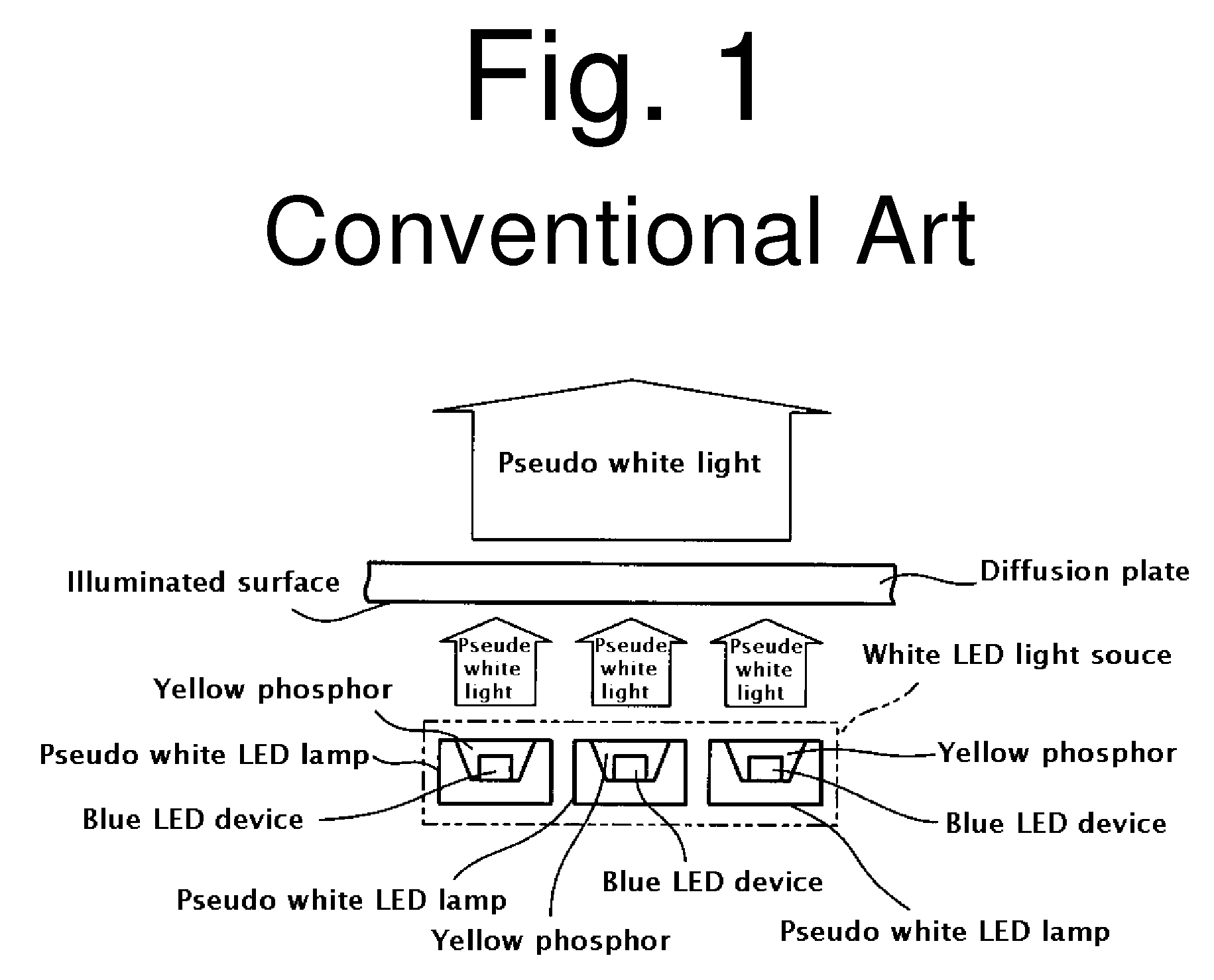
However, the produced white light may contain only limited amounts of red and green wavelength components, and therefore, is pseudo white light.
When a light source device utilizing such a method is applied as a light source for an LCD backlight, the color reproduction characteristics of the LCD may deteriorate (for example, in the case as shown in FIG. 1).
As a result of this, blue light from the blue LED device may not be effectively utilized and its utilization efficiency as well as luminous efficiency may deteriorate (for example, the case as shown in FIG. 2).
Specifically, the luminous efficiency of the red LED device may deteriorate due to temperature rise with time, and therefore, the color tone of produced white light may be shifted toward blue.
Accordingly, if a certain distance is required or desired from the light emitting surface of the LED lamps to a surface to be irradiated as a light path to ensure optical performance, miniaturization and thinning of the apparatus incorporating the LED lamps may be hampered.

Method used


Image

  • White LED light source device and LED backlight using the same
  • White LED light source device and LED backlight using the same
  • White LED light source device and LED backlight using the same

Examples


Embodiment Construction

[0042]Hereinafter, exemplary embodiments in accordance with the presently disclosed subject matter will be described with reference to the accompanying drawings of FIGS. 4 through 12 and FIGS. 14-17. The same or similar components appearing in each of the drawing Figures may be denoted by the same reference numerals / symbols.

[0043]One example of a white LED light source device made in accordance with principles of the presently disclosed subject matter can include a bluish green LED lamp and a purple LED lamp. FIG. 4 is a cross-sectional view illustrating an example of a bluish green LED lamp. FIG. 5 is a cross-sectional view illustrating an example of a purple LED lamp.

[0044]As shown in FIG. 4, the bluish green LED lamp 1a can include a lamp housing 4 and a bare LED chip (hereinafter, referred to as an LED device) 2 mounted on the housing 4 as a light-emitting body.

[0045]In this instance, the LED device 2 can be a blue LED device which can emit blue light (light having a peak wavele...


PUM


Abstract

A white LED light source device and an LED backlight using the white LED light source can produce, among other features, white light with sufficient luminous intensity, uniform color tone, and high luminous utilization efficiency. A light path for producing white light with favorable color mixture can be shortened. The white LED light source device can be configured to include a bluish green LED lamp which can emit bluish green light by the combination of a blue LED device and a green phosphor material and a purple LED lamp which can emit purple light by the combination of a blue LED device and a red phosphor material. The bluish green light from the bluish green LED lamp and the purple light from the purple LED lamp are subjected to additive color mixture to produce white light with a spectrum containing three primary color wavelength components.

Description

[0001]This application claims the priority benefit under 35 U.S.C. §119 of Japanese Patent Application No. 2006-327144 filed on Dec. 4, 2006, which is hereby incorporated in its entirety by reference.BACKGROUND[0002]1. Technical Field[0003]The presently disclosed subject matter relates to a white LED light source device and an LED backlight using the same. In particular, the disclosed subject matter relates to a white LED light source device and an LED backlight using the white LED light source device which can emit white light having a spectrum containing three primary color wavelength components of red, green, and blue light by additive color mixture of light emitted from two different LED lamps with different color tones.[0004]2. Description of the Related Art[0005]A semiconductor light-emitting device (for example, LED device) can emit light with a sharp spectrum, which can be recognized by human beings as light with color tone corresponding to a peak wavelength λp (being the wa...

Claims


Application Information

Patent Timeline
Patent Type & Authority Patents(United States)
IPC IPC(8): F21V9/00H01L33/50
CPCC09K11/584C09K11/7721C09K11/7734F21K9/00F21Y2101/02Y02B20/181F21Y2115/10Y02B20/00C09K11/77348
Inventor UENO, KAZUHIKOKOBAYASHI, NOBUYUKI
Owner STANLEY ELECTRIC CO LTD
Learn More