Lawn edging with integral electrical conductor and clip connectors
a technology of electrical conductors and edgings, applied in the direction of coupling device connections, ways, applications, etc., can solve the problems of corroding quickly, plastics that do not hold up well, and each of these materials has problems
- Summary
- Abstract
- Description
- Claims
- Application Information
AI Technical Summary
Benefits of technology
Problems solved by technology
Method used
Image
Examples
second embodiment
[0052]FIGS. 8a-13 show details of a second embodiment 320 of the lawn edging of the present invention. The edging 320 includes one or more electrical wires or conductors 300,301 which are embedded in the edging 320 and are usable to supply electric current from a power source (1000 in FIG. 16) to low voltage outdoor lighting or for other applications or curcuits. For example, FIG. 8a shows a pultruded fiberglass edging 320 having a pair of electrical conductors or wires 300,301 formed therein. One conductor 300 is located near a top edge 302 of the edging 320 and a second conductor 301 is located near a bottom edge 304 of the edging 320. The conductors 300,301 can run the full length of the edging 320. The electrical conductors 300,301 may be formed of metal wire, such as copper wire. Alternatively, both conductors or wires 300,301 may be embedded in the edging 320 in closely spaced and parallel relation near the top edge 302, near the bottom edge 304, or anywhere in between.
[0053]T...
third embodiment
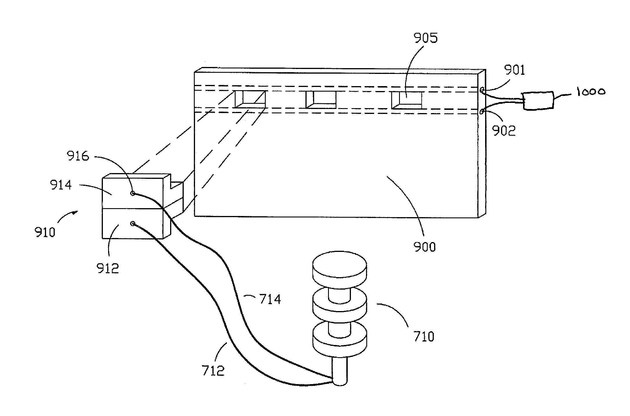
[0065]FIG. 16 discloses an alternate embodiment of the lawn edging 900. This thin fiberglass edging can include a plurality of holes 905 punched through the edging 900. These holes 905 could be formed in the edging 900 as part of the manufacturing process. The edging 900 also includes two wires 901, 902 which can be electrical conductors as well as serving to strengthen the upper portion of the edging 900. In the preferred embodiment, the electrical conductors or wires 901, 902 are located in the upper quarter of the edging 900 or approximately within one inch from the top edge of the edging 900 such that the wires 901, 902 extend above the ground when the edging 900 is installed. At installation, the wires 901, and 902 can carry low voltage DC current to power lawn mounted electrical devices such as Malibu light 710.
[0066]A clip 1010 can be press fit into the hole 905. The clip can consist of an upper portion 914 and a lower portion 912 each having an opening 916 through which pass...
fourth embodiment
[0068]FIG. 18 illustrates a fourth embodiment of the lawn edging 900, having one or more holes 905 punched therethrough or formed therein. The edging 900 includes two substantially flattened conductors 1001, 1002, forming an elongate cuboid with a length L that extends through the length of the edging 900, a height H, and a depth D. The flattened conductors 1001, 1002 may also serve to strengthen an upper portion 914 of the edging. It should be noted that upper, lower, top or bottom as used herein are references relative to the normal orientation and attitude of use of a lawn edging material. The conductors 1001, 1002 carry low voltage DC current to power electrical apparatus such as landscape lighting, outdoor speakers, and the like.
[0069]As used herein the term cuboid is intended to include wire of rectangular cross-section. In the preferred embodiment the cuboidal wire is flattened so that the wire is taller than it is wide relative to the strip of edging 900 in which it is embed...
PUM
 Abstract
Description
Claims
Application Information
 - R&D
- Intellectual Property
- Life Sciences
- Materials
- Tech Scout
- Unparalleled Data Quality
- Higher Quality Content
- 60% Fewer Hallucinations
Browse by: Latest US Patents, China's latest patents, Technical Efficacy Thesaurus, Application Domain, Technology Topic, Popular Technical Reports.
© 2025 PatSnap. All rights reserved.Legal|Privacy policy|Modern Slavery Act Transparency Statement|Sitemap|About US| Contact US: help@patsnap.com


