
Intermediate transfer device and image forming apparatus

a transfer device and image technology, applied in the direction of electrographic process apparatus, instruments, optics, etc., can solve the problems of uneven gloss in the fixed toner image, heating and compression of the toner image on the intermediate transfer member, and grainy toner image fixed on a rough surface recording medium, etc., to achieve high image density and even glossiness, without adversely affecting the performance of other devices and components

Inactive Publication Date: 2010-10-05
RICOH KK
View PDF33 Cites 8 Cited by
  • Summary
  • Abstract
  • Description
  • Claims
  • Application Information

AI Technical Summary

Benefits of technology

The present invention provides an intermediate transfer device that can produce high quality images, regardless of surface roughness of a recording medium. The device can evenly transfer a toner image onto a recording medium without affecting other devices and components. It has high durability and consumes less energy, resulting in energy saving and low cost. The device includes an intermediate transfer member, an intermediate transfer part, a heating member, a deformation member, and a recording transfer part. The invention also provides an image forming apparatus including an image bearing member, the intermediate transfer device, and a heating device. The device can transfer a toner image onto a recording medium while applying heat and pressure to the image. The excessive heat transfer member can transfer excessive heat from the deformation member.

Problems solved by technology

The degree of deformation of the toner image varies by location on the surface, and therefore, a toner image fixed on a rough-surfaced recording medium can appear grainy.
Therefore, there is a difference in surface texture between toner images fixed on convex portions and concave portions, resulting in uneven gloss in the fixed toner image.
However, a problem is that a toner image on an intermediate transfer member is heated and compressed from a toner image side.
As a result, the melted toner particles tend to adhere to the heating member, thereby causing an offset problem in which the adhered toner particles are retransferred onto the recording medium.
It is difficult to prevent the occurrence of the offset problem even if the type (i.e., surface energy) of releasing material is varied.
To reduce viscosity, the toner image needs to be heated to a higher temperature with concern of the occurrence of the offset problem.
Further, the heat may transfer to an image bearing member and increase the temperature thereof.
Consequently, toner particles contained in a developing device or a cleaning device may be aggregated on or adhered to the device, which is undesirable.
Moreover, when a greater pressure is applied at the transfixing area, components constituting the transfixing area and the intermediate transfer member need to be very durable, resulting in cost increase.
However, it is difficult to keep the temperature of the deformation member lower than that of the intermediate transfer member constantly.
Therefore, toner particles adhered to the deformation member may be retransferred onto the recording medium, resulting in production of abnormal images.
Further, such an intermediate transfer device has high durability and consumes less energy, resulting in energy saving and low cost.

Method used


Image

  • Intermediate transfer device and image forming apparatus
  • Intermediate transfer device and image forming apparatus
  • Intermediate transfer device and image forming apparatus

Examples


Embodiment Construction

[0046]Example embodiments will now be described in detail referring to the drawings, wherein like reference numerals designate identical or corresponding parts throughout the several views thereof.

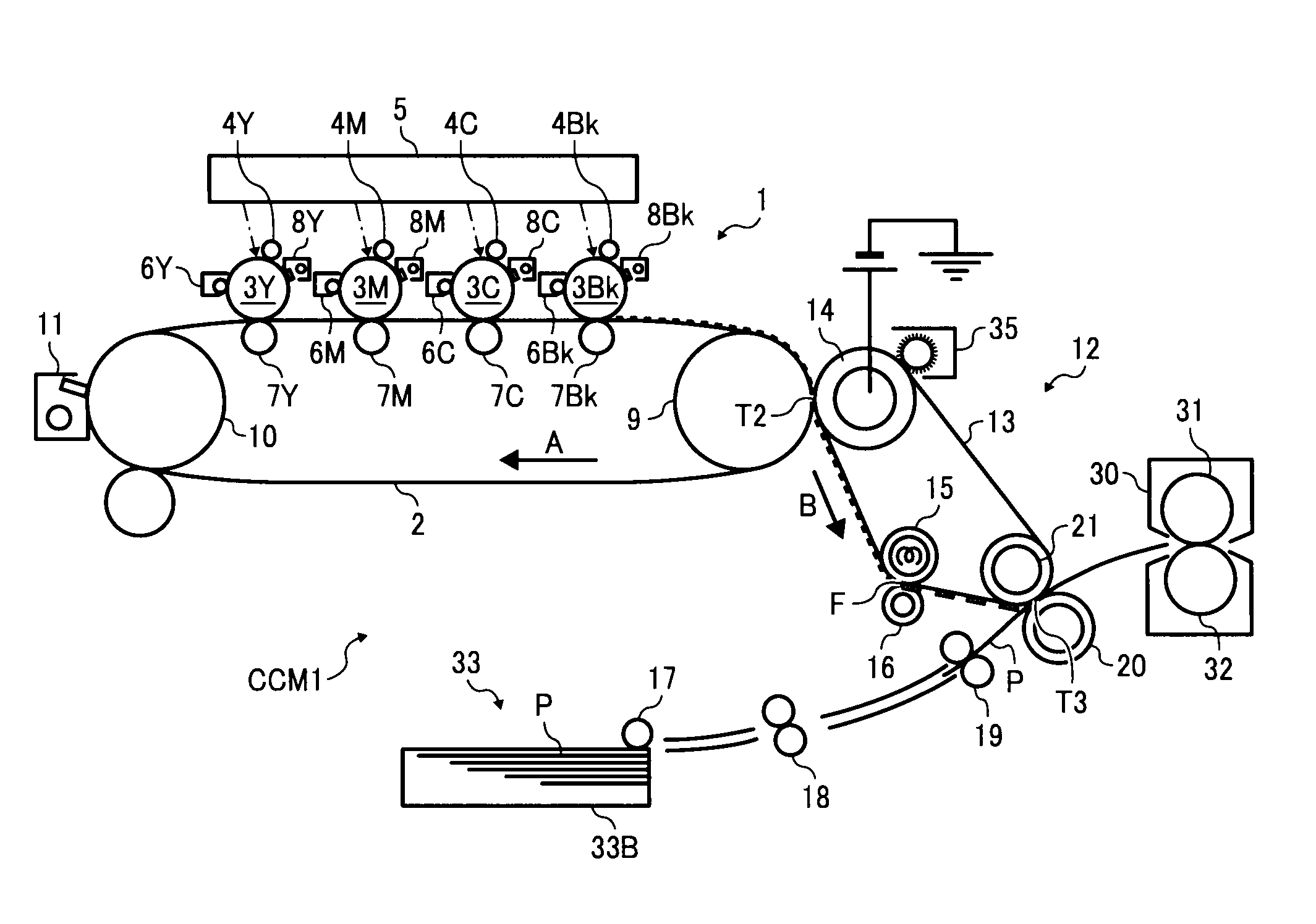
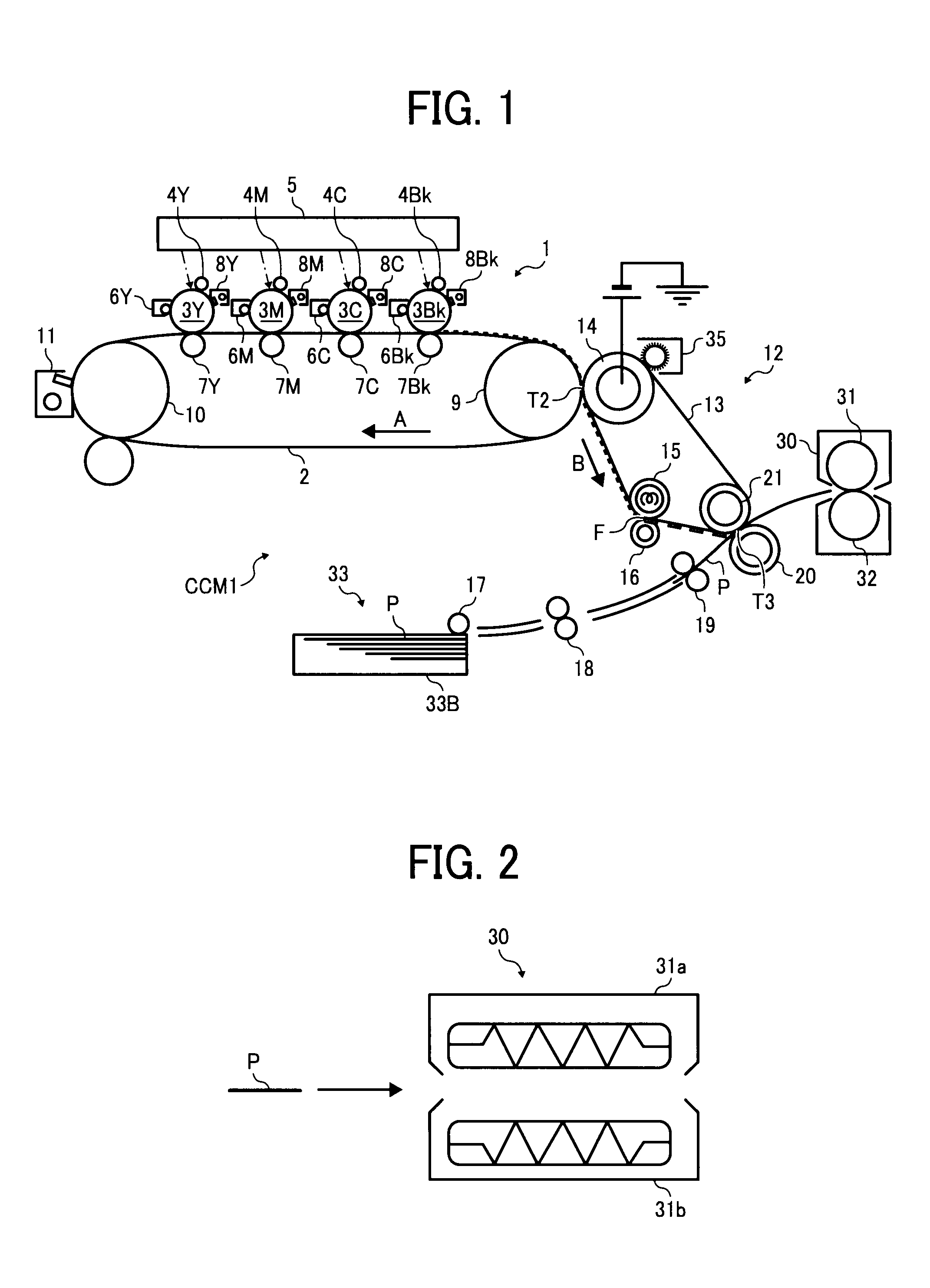
[0047]FIG. 1 is a schematic view illustrating a tandem color copier as an example embodiment of an image forming apparatus of the present invention.

[0048]A tandem color copier CCM1 illustrated in FIG. 1 includes an image forming part 1 in the central part, an intermediate transfer device 12, and a paper feed part 33 beneath the intermediate transfer device 12. The image forming part 1 includes an intermediate transfer belt 2 having a transfer surface stretched in a horizontal direction. The intermediate transfer belt 2 is stretched taut by a driving roller 9 and a driven roller 10, and is rotatable in a direction indicated by arrow A in FIG. 1.

[0049]Above the transfer surface of the intermediate transfer belt 2, drum-shaped photoconductors (i.e., image bearing members) 3Y, 3M, 3C, and 3Bk ...


PUM


Abstract

An intermediate transfer device including an intermediate transfer member, an intermediate transfer part configured to transfer a toner image from an image bearing member onto the intermediate transfer member, a heating member configured to heat the intermediate transfer member to apply heat to the toner image thereon, a deformation member configured to apply pressure to the heated toner image on the intermediate transfer member, and a recording transfer part configured to transfer the compressed toner image from the intermediate transfer member onto a recording medium.

Description

CROSS-REFERENCE TO RELATED APPLICATIONS[0001]This document claims priority from and contains subject matter related to Japanese Patent Application Nos. 2007-210478 and 2007-238580, filed on Aug. 10, 2007 and Sep. 13, 2007, respectively, the entire contents of each of which are hereby incorporated herein by reference.BACKGROUND[0002]1. Field of the Invention[0003]The present invention relates to an intermediate transfer device that transfers a toner image from an image bearing member onto a recording medium using an intermediate transfer member, and to an image forming apparatus using the intermediate transfer device.[0004]2. Description of the Background[0005]In a typical image forming apparatus, single-color toner images of different colors are sequentially formed on an image bearing member and sequentially transferred onto an intermediate transfer member so that a full-color toner image (hereinafter “toner image”) in which the single-color toner images are superimposed on one anot...

Claims


Application Information

Patent Timeline
Patent Type & Authority Patents(United States)
IPC IPC(8): G03G15/16
CPCG03G15/161G03G15/169G03G15/1605
Inventor SOMEYA, YUKIMICHISHIMIZU, MISAKI
Owner RICOH KK
Learn More