
Light sensing circuit, backlight control apparatus having the same, and liquid crystal display device having the same

a technology of backlight control and light sensing circuit, which is applied in the direction of static indicating devices, non-linear optics, instruments, etc., can solve problems such as power was

Active Publication Date: 2010-09-28
LG DISPLAY CO LTD
View PDF20 Cites 4 Cited by
  • Summary
  • Abstract
  • Description
  • Claims
  • Application Information

AI Technical Summary

Benefits of technology

This solution enables precise detection of optical amount variations, improving the reliability of brightness control and reducing power consumption by adjusting backlight intensity based on ambient light conditions without relying on resistors, thus enhancing energy efficiency and user experience.

Problems solved by technology

However, the conventional backlight has been constructed so as to maintain a brightness constant regardless of a peripheral brightness, thereby wasting power.

Method used


Image

  • Light sensing circuit, backlight control apparatus having the same, and liquid crystal display device having the same
  • Light sensing circuit, backlight control apparatus having the same, and liquid crystal display device having the same
  • Light sensing circuit, backlight control apparatus having the same, and liquid crystal display device having the same

Examples


Embodiment Construction

[0028]Reference will now be made in detail to the preferred embodiments of the present invention, examples of which are illustrated in the accompanying drawings.

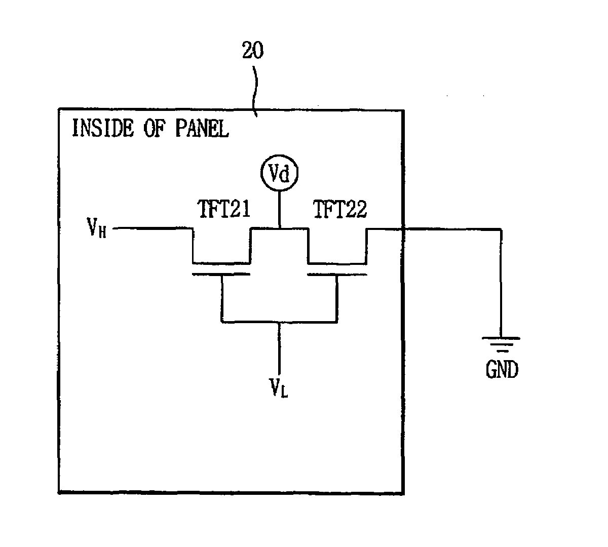
[0029]FIG. 2 is a circuit diagram showing a light sensing circuit for an LCD device. As shown, a light sensing circuit 20 comprises a first MOS-transistor and a second MOS-transistor serially connected to each other between a first power terminal (VH) and a ground terminal (GND), in which a second power terminal (VL) is connected to each gate terminal of the first MOS-transistor and the second MOS-transistor, and an optical amount detecting terminal (Vd) is connected to a common connection point between a drain terminal of the first MOS-transistor and a source terminal of the second MOS-transistor.

[0030]The light sensing circuit 20 will be explained in more detail with reference to FIGS. 2 and 3.

[0031]As shown in FIG. 2, in the light sensing circuit 20, an amorphous-silicon type (a-Si) first MOS-transistor TFT21 is connected...


PUM


Abstract

A light sensing circuit capable of enhancing a reliability by lowering a dependency on a temperature change without using a resistor, a backlight control apparatus having the same, and an LCD device having the same. The light sensing circuit includes a first MOS-transistor; and a second MOS-transistor serially connected to the first MOS-transistor between a first power terminal and a ground terminal, in which a second power terminal is connected to each gate terminal of the first MOS-transistor and the second MOS-transistor, and an optical amount detecting terminal is connected to a common connection point between a drain terminal of the first MOS-transistor and a source terminal of the second MOS-transistor.

Description

RELATED APPLICATION[0001]The present disclosure claims the benefit of priority of Korean Application No. 10-2006-057131, filed on Jun. 23, 2006, which is herein expressly incorporated by reference in its entirety.BACKGROUND[0002]1. Technical Field[0003]The present invention relates to a light sensing circuit capable of measuring an optical amount, a backlight control apparatus having the same, and a liquid crystal display (LCD) device having the same, and more particularly, to a light sensing circuit capable of lowering a dependency on a temperature change without using a resistor, a backlight control apparatus having the same, and an LCD device having the same.[0004]2. Description of the Related Art[0005]Generally, an LCD device serves to display a desired image by controlling an amount of light that passes through a liquid crystal layer by controlling an arrangement of a liquid crystal molecule having a refractivity anisotropy using an electric field.[0006]The LCD device consists ...

Claims


Application Information

Patent Timeline
Patent Type & Authority Patents(United States)
IPC IPC(8): G09G3/36
CPCG09G3/3406G09G2320/0626G09G2330/021G09G2360/144G02F1/133
Inventor YOON, JEONG-WONMOON, SU-HWAN
Owner LG DISPLAY CO LTD
Learn More