
Method and device for excavating submerged stratum

a technology of submerged stratum and method, which is applied in the direction of optical radiation measurement, nuclear engineering, and wellbore/well accessories, etc., can solve the problems of inability to irradiate enough energy for stratum excavation, the laser beam may not pass through the liquid, etc., and achieve the effect of reducing the energy transfer of one fiber, reducing the load on a single fiber, and increasing the number of fibers

Inactive Publication Date: 2010-09-28
JAPAN DRILLING CO LTD +2
View PDF32 Cites 47 Cited by
  • Summary
  • Abstract
  • Description
  • Claims
  • Application Information

AI Technical Summary

Benefits of technology

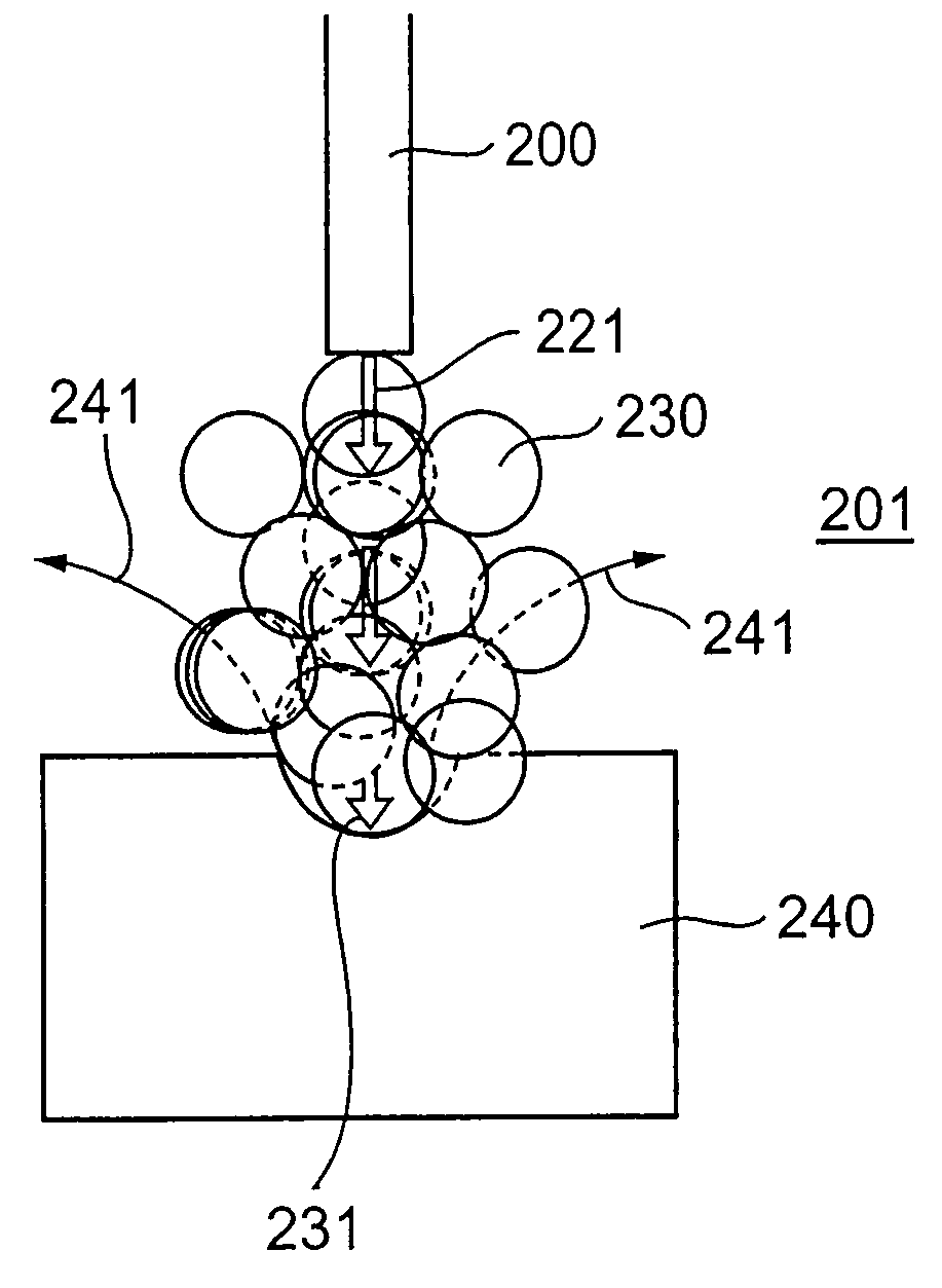
"The present invention provides a method for excavating a submerged stratum using a laser beam. The method includes using a first laser beam to generate a laser-induced shock wave, jet stream, bubble flow, or acoustic wave in liquid. The laser beam passes through a bubble created by the laser beam, and the energy of the laser beam is sufficient to destroy the stratum. The method also includes using a second laser beam to irradiate the stratum. The second laser beam may be a pulsed laser or a continuous-wave laser. The device for excavating a submerged stratum includes a laser oscillation means, laser transmission means, and laser irradiation means. The method and device can efficiently excavate submerged strata and provide a synergistic effect."

Problems solved by technology

However, when turbidity in the liquid becomes large due to the excavated stratum during stratum excavation, there occurs a problem that the laser beam may not transmit through the liquid.
In a laser beam generated by a laser oscillator and transmitted through a fiber, incident energy to the fiber decays as a transmission distance is longer, and then there may be a problem that it becomes impossible to irradiate energy sufficient for stratum excavation.

Method used


Image

  • Method and device for excavating submerged stratum
  • Method and device for excavating submerged stratum
  • Method and device for excavating submerged stratum

Examples


Embodiment Construction

[0070]First, parameters representative of laser strength will be described.

[0071]A laser output (average output) P is an energy per sec. In a laser turned on and off intermittently, the laser output P is expressed as follows:

P=E×ν  (1)

Where, P is the laser output (W), E is a pulse energy (J), and ν is a repetition frequency. Increase in the laser output P may be achieved by increasing either the pulse energy E or the repetition frequency ν.

[0072]Next, a fluence F is a value indicating the pulse energy divided by an area.

F=E / S  (2)

Where, F is the fluence (J / cm2), E is the pulse energy (J) and S is the area (cm2).

[0073]Next, a laser strength I is a value indicating the fluence F divided by a pulse width.

I=E / (St)  (3)

Where, I is the laser strength (W / cm2) and t is the pulse width (sec).

[0074]A spot diameter of laser irradiation is determined by a diameter of a fiber core when a fiber is used. When a lens is used, a desired focused diameter ω0 is obtained from the following approximate ...


PUM

PropertyMeasurementUnit
forceaaaaaaaaaa
laser-induced aaaaaaaaaa
wavelengthaaaaaaaaaa

Abstract

An excavation technique for a stratum capable of excavating a submerged stratum such as a layer containing an underground resource by using laser irradiation in liquid is provided. In this technique, a laser beam transmitted through laser transmission means 20 is irradiated in liquid 90 in form of a laser beam having a wavelength with high absorptance of the liquid 90 by laser-induced bubble generation means 35, generating a bubble flow 36, thus excavation of a submerged stratum may be carried out by using a laser-induced destruction effect. Moreover, a laser beam 41 having low absorptance of the liquid 90 is irradiated by laser irradiation means 39 and passed through the bubble flow 36, thereby applying a thermal effect to a stratum to destroy rock and excavate the stratum. The destruction effect and the thermal effect also may be cooperatively worked.

Description

TECHNICAL FIELD[0001]The present invention relates to a method and device for excavating a submerged stratum, which is basically a technique used for development of a submerged underground resource, for example. More generally, the present invention is a technique applicable to the fields of civil engineering and architecture, which relates to a technique of excavating a submerged stratum using laser irradiation in liquid.BACKGROUND ART[0002]Conventionally, an excavation technique of a stratum such as the one used for boring a stratum employs, regardless of in liquid or air, turning force, impactive force, water jet or the like.[0003]A technique employing the turning force uses an excavation bit in a ground boring machine (for example, see Patent Document 1). In this technique, the excavation bit is provided on the front edge of a rotational driveshaft and the ground is excavated by rotation and forward movement of the excavation bit. A power source for the ground excavation is rota...

Claims


Application Information

Patent Timeline
Patent Type & Authority Patents(United States)
IPC IPC(8): E02F3/90E02F1/00E21C37/16A61N5/00B23K26/12E21B7/14E21C37/18
CPCE21B7/00E21B7/14E21B7/18E21B7/24E21B43/285E21C45/00
Inventor KOBAYASHI, TOSHIOTAKAYAMA, KAZUYOSHIUEDA, KEN-ICHIOTOMO, KAZUHISAUETAKE, SHIGEHITO
Owner JAPAN DRILLING CO LTD
Learn More