
Battery charger with battery life judging function

a battery charger and function technology, applied in the field of battery chargers, can solve the problems of difficult to judge whether the battery life has expired, and the limit of the number of times the battery can be charged and discharged,

Inactive Publication Date: 2010-09-21
KOKI HLDG CO LTD
View PDF8 Cites 4 Cited by
  • Summary
  • Abstract
  • Description
  • Claims
  • Application Information

AI Technical Summary

Benefits of technology

[0007]In view of the foregoing, it is an object of the present invention to provide a battery life judging device capable of reliably determining when the life of a battery has expired, regardless of the type of battery.
[0008]It is another object of the present invention to provide a battery life judging device that can easily notify a user when the battery is in a deteriorated state.
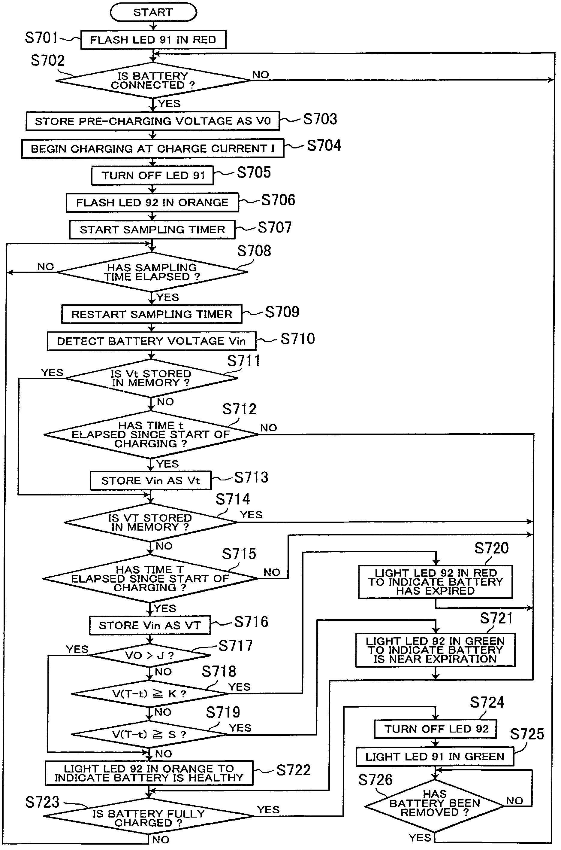
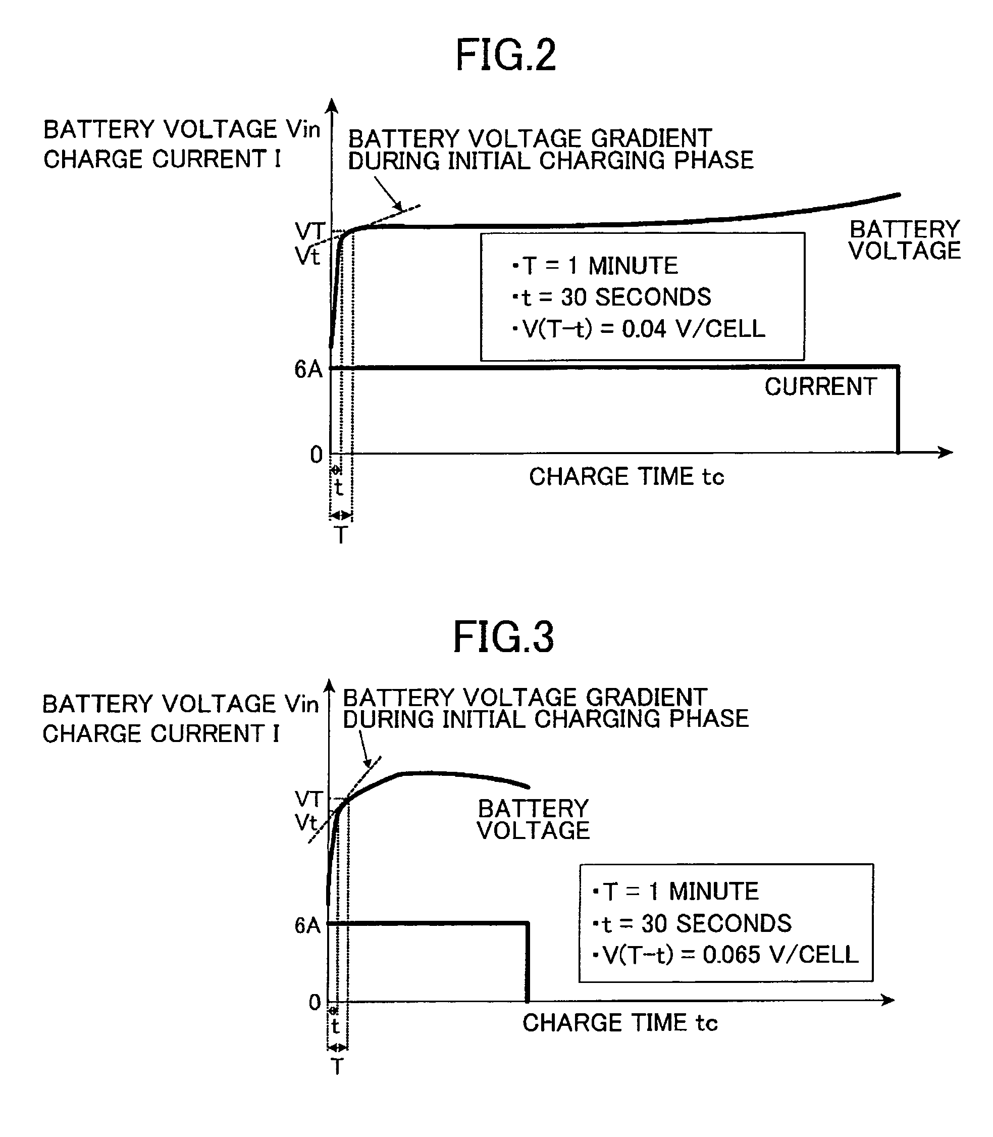
[0010]The battery life judging device having the construction described above establishes a first prescribed value for a battery voltage gradient and judges that the life of a battery has expired when the battery voltage gradient in the initial charging phase is greater than or equal to the first prescribed value. Therefore, the present invention increases the number of types of batteries for which expiration of life can be determined.
[0019]The battery charger having the battery life judging functionality can reliably determine the life of various batteries within a short amount of time. The battery charger can also easily notify a user when the state of the battery has deteriorated.

Problems solved by technology

Since the initial properties of the battery deteriorate in this way, there is a limit to the number of times that the battery can be charged and discharged.
However, since batteries exhibit different voltage behavior according to the type of battery, internal material, manufacturing method, and the like, it is often difficult to judge whether the battery life has expired based simply on whether the battery voltage exceeds the life judging threshold.

Method used


Image

  • Battery charger with battery life judging function
  • Battery charger with battery life judging function
  • Battery charger with battery life judging function

Examples


Embodiment Construction

[0028]Next, a preferred embodiment of the present invention will be described while referring to the accompanying drawings. A battery life judging device according to the preferred embodiment functions to determine when the battery life has expired for a variety of batteries and is provided as an additional function in a charging device used to charge battery packs or the like configured of nickel-cadmium batteries or nickel-metal-hydride batteries.

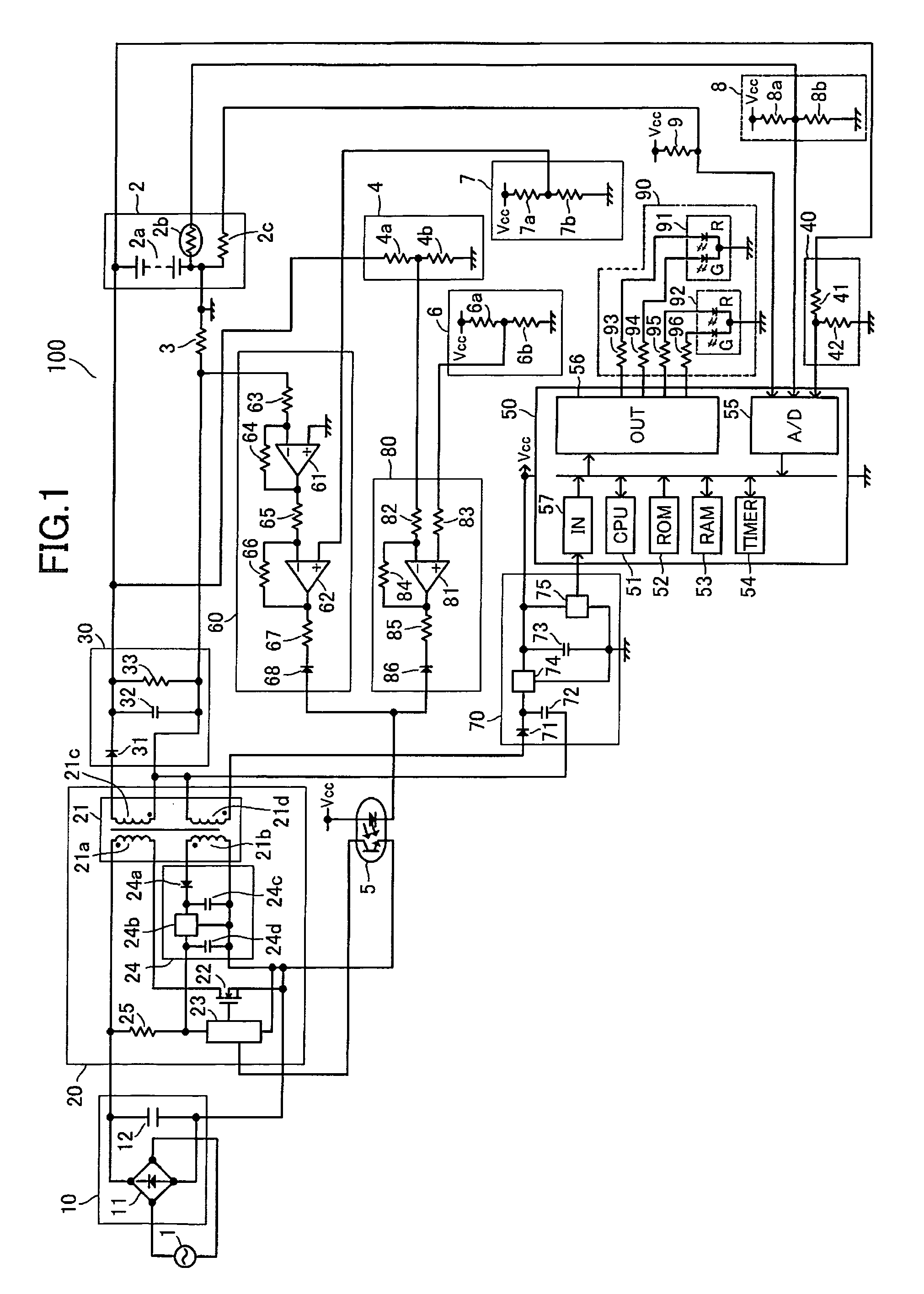
[0029]First, a charging device 100 will be described with reference to FIG. 1. The charging device 100 is connected to an AC (alternating current) power source 1 for charging a battery pack 2. The charging device 100 has a power supply circuit configured of a primary rectifying / smoothing circuit 10, a switching circuit 20, and a secondary rectifying / smoothing circuit 30 for supplying power to charge the battery pack 2.

[0030]Built inside the battery pack 2 are a battery 2a having a plurality of cells connected in series, a temperature dete...


PUM


Abstract

A charging device includes a battery voltage detecting circuit for detecting the voltage of a battery pack; and a microcomputer having RAM for temporarily storing a battery voltage detected by the battery voltage detecting circuit, and a CPU for calculating a battery voltage gradient from the battery voltage detected by the battery voltage detecting circuit and a battery voltage sampled a prescribed time earlier. The charging device determines that the life of the battery has expired when the voltage of the battery pack prior to charging is less than or equal to a prescribed value J and the battery voltage gradient within a prescribed time period after the start of charging is greater than or equal to a first prescribed value K. The charging device also includes a display circuit for notifying the user when the life of the battery pack has deteriorated.

Description

BACKGROUND OF THE INVENTION[0001]1. Field of the Invention[0002]The present invention relates generally to a battery charger for nickel-metal-hydride batteries or other secondary batteries, and more particularly, to a battery life judging device employed in the battery charger.[0003]2. Description of the Related Art[0004]Rechargeable batteries are commonly used as a power supply for portable devices. When a battery in such a device loses its capacitance, the battery is removed from the portable device, charged with a charging device, and subsequently remounted in the portable device. By repeating this process, the rechargeable battery can be used numerous times. However, as the charging / discharging cycle is repeated, the discharge capacity of the battery declines, as shown in FIG. 5. Since the initial properties of the battery deteriorate in this way, there is a limit to the number of times that the battery can be charged and discharged. Conventionally, users have had to determine w...

Claims


Application Information

Patent Timeline
Patent Type & Authority Patents(United States)
IPC IPC(8): H02J7/00
CPCG01R31/3648G01R31/3679G01R31/362G01R31/3682G01R31/392G01R31/3646G01R31/3835
Inventor ARADACHI, TAKAOTAKANO, NOBUHIROFUNABASHI, KAZUHIKO
Owner KOKI HLDG CO LTD
Learn More