Spray deposited heater element

a heating element and spray technology, applied in the direction of resistors, superimposed coating processes, electric heating of furnaces, etc., can solve the problems of other elements being prone to seepage of molten polymer materials, bulky heater elements, and inability to fit into heating areas

Inactive Publication Date: 2010-09-21
HUSKY INJECTION MOLDING SYST LTD
View PDF22 Cites 14 Cited by
  • Summary
  • Abstract
  • Description
  • Claims
  • Application Information

AI Technical Summary

Problems solved by technology

However, many of these heating elements rely upon intimate contact with the surface to be heated to conduct heat and in some cases it may even be necessary to apply a heat transfer compound between the heating element and the surface to be heated.
In addition, the heater elements may be bulky with respect to the clearances within which the elements must fit and additional design space to accommodate the elements may need to be provided.
Furthermore, some types of heater elements may be unable to fit into areas where heating is desired.
Other elements may also be prone to molten polymer material seeping between the heating element and the surface to be heated.
Such problems may reduce the efficiency of these heaters.
Further, polymer dust generated from molding process can cover wire wound heaters and cause it to overheat due to surface contamination.

Method used


Image

  • Spray deposited heater element
  • Spray deposited heater element
  • Spray deposited heater element

Examples


Embodiment Construction

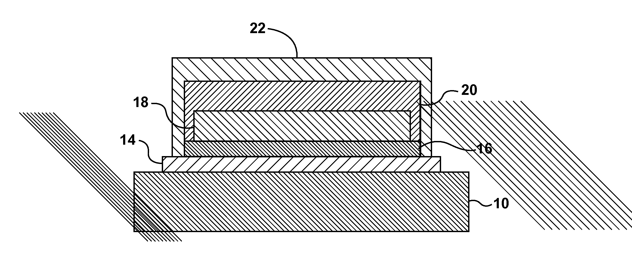
[0018]The present disclosure relates to providing a spray deposited heater in a molding apparatus. A polymeric material may be supplied wherein it is desirable to heat and maintain the polymeric material at a viscosity sufficient to allow for the polymeric material to flow in the molding apparatus. In other molding processes, a polymeric material may be supplied wherein it is desirable to heat the polymeric material once the material has reached the mold, such that the material cures or crosslinks. Accordingly, due to the various process requirements, different components of a molding apparatus may require heating elements. For example, an injection molding machine may utilize an injection unit nozzle, mold, a heated sprue bushing or a hot runner manifold and nozzles. However, the spaces around these components may be limited and the components may be subject to some degree of movement during an injection molding cycle. Furthermore, some of these components may have a complex geomet...


PUM

PropertyMeasurementUnit
thicknessaaaaaaaaaa
thicknessaaaaaaaaaa
thicknessaaaaaaaaaa

Abstract

A heater that may be applied to a substrate. The heater may include a graduating material deposited on at least a portion of a substrate, a resistive material and a thermal barrier dielectric coating. The resistive material may include at least two resistive compositions, wherein the resistivity of the material may be altered by varying the composition in given areas.

Description

TECHNICAL FIELD OF THE INVENTION[0001]The present disclosure relates to a spray deposited heating element and a method of applying said heater element.DESCRIPTION OF THE RELATED ART[0002]In various molding processes, a polymeric material may be supplied wherein it is desirable to heat and maintain the polymeric material at a viscosity sufficient to allow for the polymeric material to flow in the molding apparatus. In other molding process, a polymeric material may be supplied wherein it is desirable to heat the polymeric material once the material has reached the mold, such that the material cures or crosslinks. Accordingly, different aspects of the molding apparatus may utilize heating elements. For example, in an injection molding machine, it may be necessary to heat a barrel, nozzle, a sprue bushing, a hot runner manifold, including hot runner nozzles, and portions of a mold.[0003]Heater elements may include items such as cartridge, heater bands, coiled cable heaters, silicon rub...

Claims


Application Information

Patent Timeline
Patent Type & Authority Patents(United States)
IPC IPC(8): F27D11/00H01C1/12
CPCC23C28/321C23C28/322C23C28/34C23C28/341C23C28/345C23C28/3455C23C28/36C23C28/324B29C45/72B29C45/2737
Inventor PILAVDZIC, JIMVON BUREN, STEFAN
Owner HUSKY INJECTION MOLDING SYST LTD
Why Eureka
Try Eureka