
Drive control apparatus for controlling drive of inductive load and drive control method for controlling the same

a technology of inductive load and control apparatus, which is applied in the direction of pulse generators, pulse techniques, instruments, etc., can solve the problems of increasing manufacturing costs, reduce the sliding resistance of linear solenoid, reduce the increment and decrement of current ripple amount, and shorten the current ripple period of inductive load due to pwm control

Active Publication Date: 2010-09-14
FUJI ELECTRIC CO LTD
View PDF7 Cites 4 Cited by
  • Summary
  • Abstract
  • Description
  • Claims
  • Application Information

AI Technical Summary

Benefits of technology

[0043]As described above, the fluctuation period of the reference current value is controlled such that the fluctuation period of the reference current value is set to be longer than the fluctuation period of the current flowing through the inductive load caused by the PWM control. The control described above makes it possible to provide the reference current value with a current ripple amount for minimizing the sliding resistance of a linear solenoid. Therefore, the fluctuation period of the current flowing through the inductive load due to the PWM control is shortened. Even when the characteristics of the inductive loads are different, it is possible to reduce the increment and decrement of the current ripple amount affected by the characteristics of the inductive load. Therefore, it is possible to reduce the sliding resistance of the linear solenoid and to change the current ripple amount on a same circuit so that the current ripple amount may fall within the detectable range of the current flowing through the inductive load.

Problems solved by technology

Therefore, it is necessary to prepare an IC for every inductive load 15, thereby increasing the manufacturing costs.

Method used


Image

  • Drive control apparatus for controlling drive of inductive load and drive control method for controlling the same
  • Drive control apparatus for controlling drive of inductive load and drive control method for controlling the same
  • Drive control apparatus for controlling drive of inductive load and drive control method for controlling the same

Examples


first embodiment

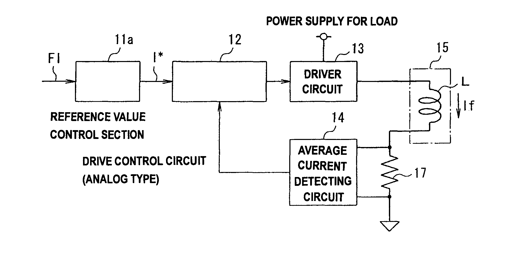
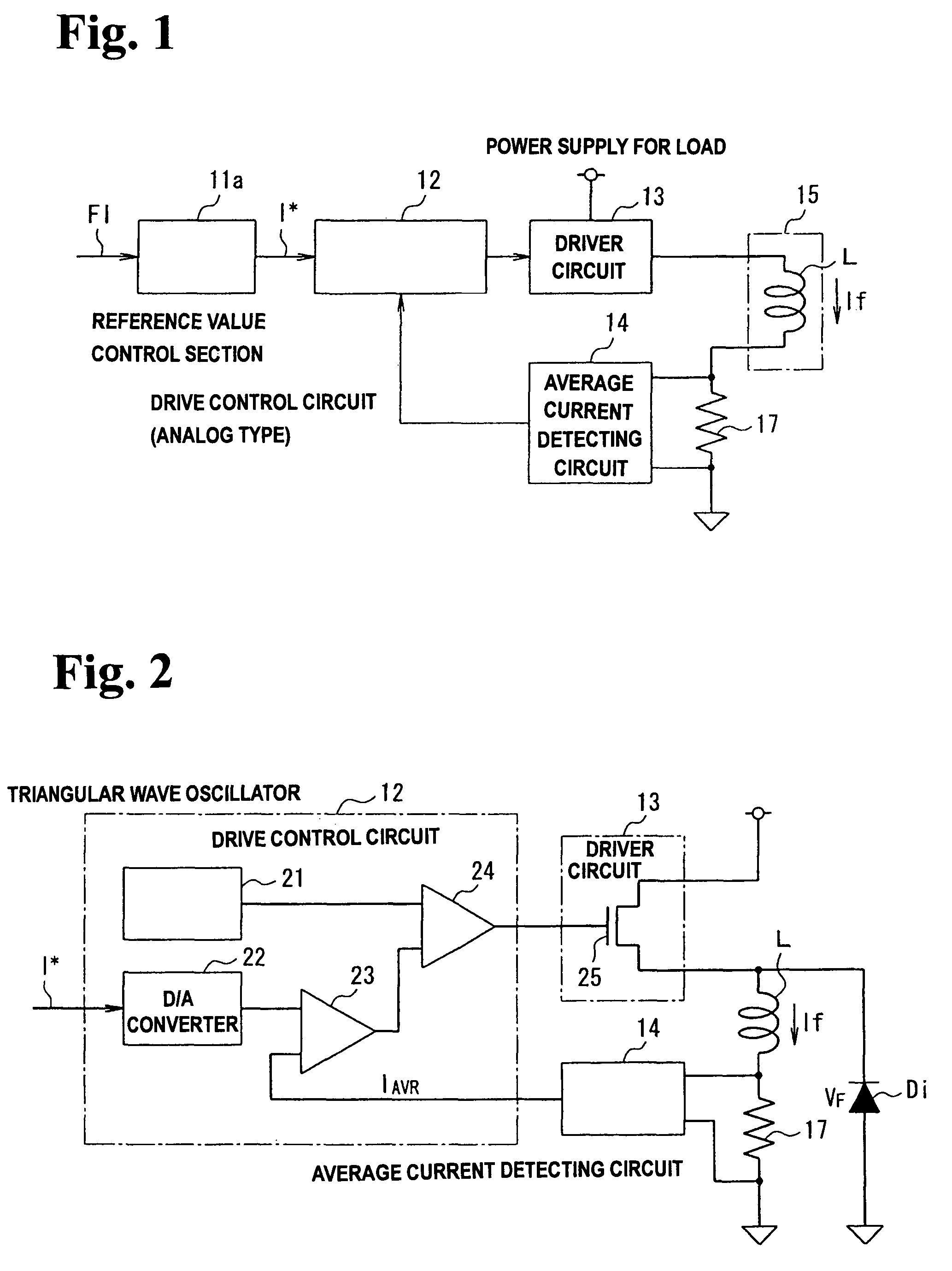
[0070]FIG. 1 is a block diagram briefly describing a closed loop control system, to which a drive control apparatus according to the invention for controlling the drive of an inductive load is applied.

[0071]In FIG. 1, driver circuit 13 is connected to the first end of inductive load 15. Current detecting resistor 17 is connected in series to the second end of inductive load 15. Drive control circuit 12 that conducts a PWM control by analog data processing is disposed in the front stage of driver circuit 13. Reference value control section 11a is disposed in the front stage of drive control circuit 12.

[0072]Average current detecting circuit 14 is connected between the first and second ends of current detecting resistor 17. The output from average current detecting circuit 14 is connected to drive control circuit 12.

[0073]For controlling the drive of inductive load 15, drive control circuit 12 changes current If flowing through inductive load 15 by the PWM control so that current If f...

second embodiment

[0108]FIG. 13 is a block diagram briefly describing a closed loop control system, to which a drive control apparatus according to the invention for controlling the drive of an inductive load is applied.

[0109]In FIG. 13, reference value control section 11b is disposed according to the second embodiment in substitution for reference value control section 11a in FIG. 1. In FIG. 1, the set current value data FI is fed to reference value control section 11a as a variable. In contrast, the set current value data FI and a current ripple waveform control data FR are fed to reference value control section 11b as variables in FIG. 13. The current ripple waveform control data FR specifies the current ripple amount of the reference current value I*.

[0110]FIG. 14 is a block diagram briefly describing the structure of reference value control section 11b shown in FIG. 13.

[0111]In FIG. 14, reference value control section 11b includes period and time data storage section 31b, current ripple data sto...

third embodiment

[0113]FIG. 15 is a block diagram briefly describing the structure of reference value control section 11c according to the invention.

[0114]In FIG. 15, reference value control section 11c according to the third embodiment includes period and time data storage section 31c, current ripple data storage section 32c, set current data storage section 33c, timing generator circuit 34c, and signal generator circuit 35c. Period and time data storage section 31c stores the waveform control data FR1 of the reference current value I* as a variable. Current ripple data storage section 32c stores the current ripple data FR2 of the reference current value I* as a variable. Set current data storage section 33c stores the set current value data FI as a variable. Timing generator circuit 34c generates the generation timing for generating the reference current value I*. Signal generator circuit 35c generates the waveform of the reference current value I*. The waveform control data FR1 specifies the peri...


PUM


Abstract

A drive control apparatus controls a drive of an inductive load having a current flowing therethrough. The drive control apparatus includes a drive control device for controlling a variation of the current flowing through the inductive load within a certain period by Pulse Width Modulation control so as to come close to a reference current value, and a reference value control device for controlling a fluctuation period of the reference current value and making the fluctuation period of the reference current value longer than that of the current flowing through the inductive load by the Pulse Width Modulation control.

Description

BACKGROUND OF THE INVENTION AND RELATED ART STATEMENT[0001]The present invention relates to a drive control apparatus and a drive control method for controlling the drive of an inductive load. Specifically, the invention relates to a driver control apparatus and a drive control method, which are applied preferably for controlling the drive of an inductive load such as a solenoid actuator used in automatic transmissions for automobiles. Hereinafter, the drive control apparatus for controlling the drive of an inductive load will be referred to simply as the “drive control apparatus”. Also, the drive control method for controlling the drive of an inductive load will be referred to simply as the “drive control method”.[0002]In driving an inductive load such as the solenoid actuator used in automatic transmissions for automobiles, the current flowing through the inductive load is controlled by pulse width modulation (hereinafter referred to as “PWM”).[0003]FIG. 21 is a block diagram brie...

Claims


Application Information

Patent Timeline
Patent Type & Authority Patents(United States)
IPC IPC(8): H03K3/00
CPCH02M3/156H02M2003/1555H02M3/1555
Inventor AKAHANE, MASASHIIWAMOTO, MOTOMITSUNISHIO, HARUHIKONISHIO, MINORUTOBISAKA, HIROSHI
Owner FUJI ELECTRIC CO LTD
Learn More