
Fine-resolution edge-extending pulse width modulator

a pulse width modulator, fine resolution technology, applied in pulse manipulation, pulse technique, code conversion, etc., can solve the problems of low-power applications, unsuitable high-efficiency applications, and high-cost designs

Active Publication Date: 2010-09-07
NAT SEMICON CORP
View PDF4 Cites 29 Cited by
  • Summary
  • Abstract
  • Description
  • Claims
  • Application Information

AI Technical Summary

Problems solved by technology

This makes the design expensive and unsuitable for high-efficiency, low-power applications.
However, such complex clocking systems generally result in various logic-timing problems.

Method used


Image

  • Fine-resolution edge-extending pulse width modulator
  • Fine-resolution edge-extending pulse width modulator
  • Fine-resolution edge-extending pulse width modulator

Examples


Embodiment Construction

[0024]FIGS. 1 through 13B, discussed below, and the various embodiments used to describe the principles of the present invention in this patent document are by way of illustration only and should not be construed in any way to limit the scope of the invention. Those skilled in the art will understand that the principles of the present invention may be implemented in any suitably arranged device.

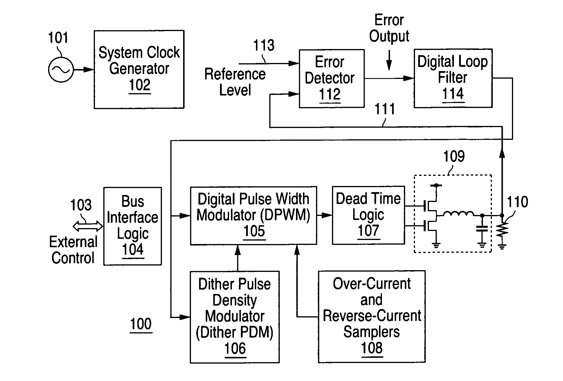
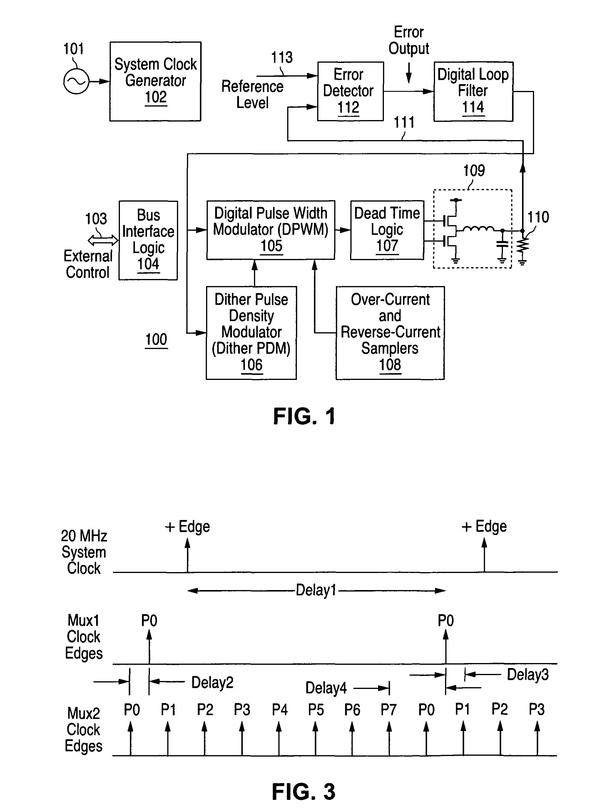
[0025]FIG. 1 is a high-level block diagram of a digital switcher core according to one embodiment of the present invention. Digital switcher 100 includes an external timing reference 101 employed by a system clock generator 102 to generate clock signals for various functional units (clock signal transmission paths are not shown for simplicity and clarity). Digital switcher 100 also includes input(s) 103 for external control signals, received at a bus interface logic unit 104 and employed to control various functional units (control signal paths are also not shown for simplicity and clarity). ...


PUM


Abstract

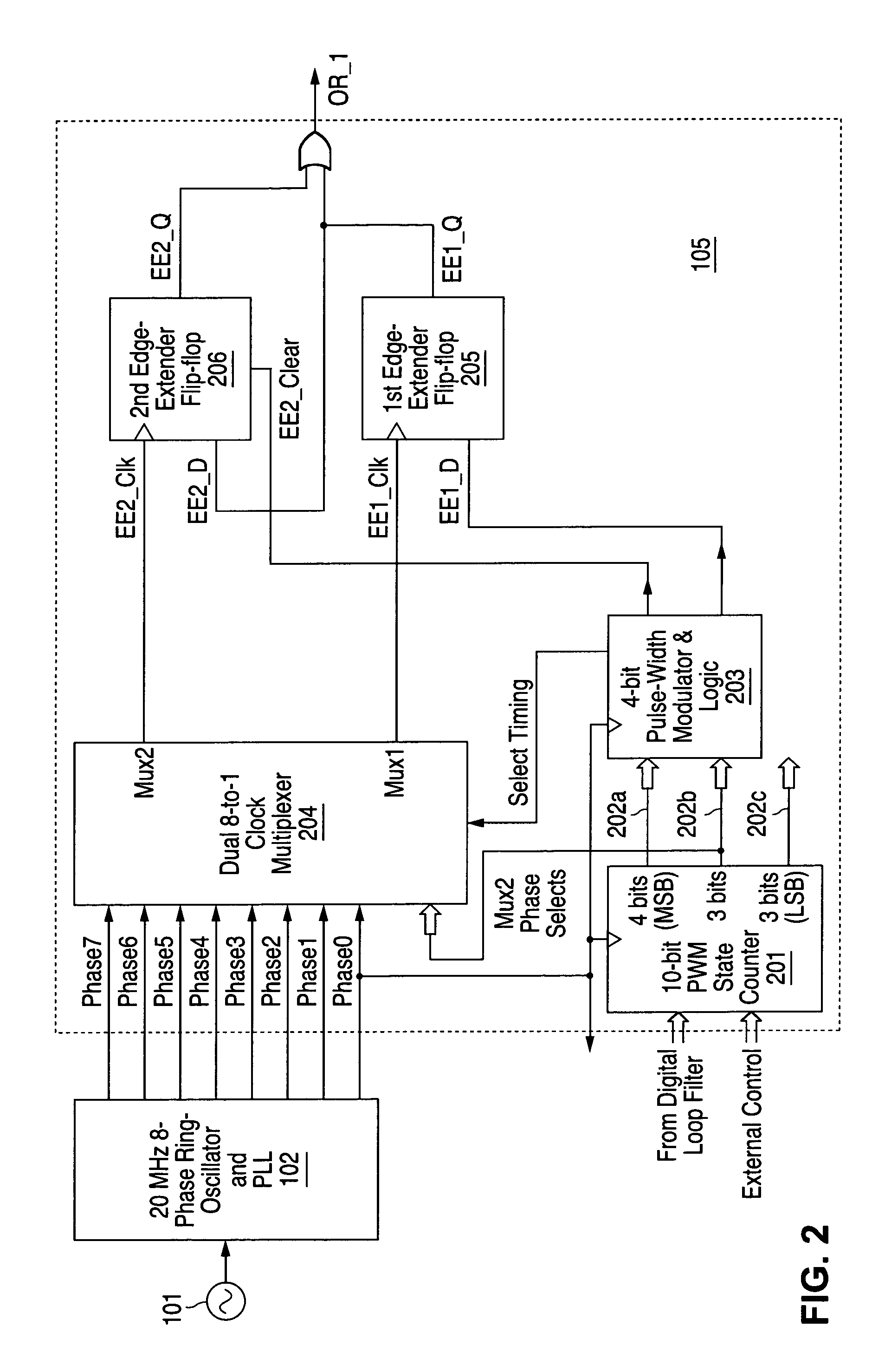
Fine resolution pulse width modulation is achieved through feed-forward edge extending logic. A ring-oscillator produces phase-shifted versions of a system clock and two latches operate in parallel with the system clock output from the multiplexer clocking a first latch and a selected phase-shifted version of the system clock from the multiplexer clocking the second latch. The first latch receives a coarse output pulse equal to a selected number of clock periods as an input, while the second latch receives the output of the first latch as an input. A logic gate combines outputs from the latches to produce the output pulse having a trailing edge extended by a selected number of phase divisions.

Description

CROSS-REFERENCE TO RELATED APPLICATIONS[0001]This application is related to the subject matter of commonly-assigned copending U.S. patent application Ser. Nos. 11 / 204,297 entitled DITHER SCHEME USING PULSE-DENSITY MODULATION (DITHER PDM) and 11 / 204,284, entitled DIGITAL DEAD-TIME CONTROLLER FOR PULSE WIDTH MODULATORS, both filed on an even date herewith. The content of the above-identified applications is hereby incorporated by reference.TECHNICAL FIELD OF THE INVENTION[0002]The present invention is directed, in general, to digital pulse width modulation and, more specifically, to multi-phase clocking, fine-resolution edge extending pulse width modulation.BACKGROUND OF THE INVENTION[0003]Pulse width modulators (PWMs) are a key circuit block in building power switching regulators. Conventional, analog technology pulse width modulator circuits must be adjusted to compensate for process-voltage-temperature (PVT) variations, while digital pulse width modulators offer much higher circuit...

Claims


Application Information

Patent Timeline
Patent Type & Authority Patents(United States)
IPC IPC(8): H03K7/08
CPCH03K7/08H03M1/0639H03M1/68H03M1/822
Inventor WONG, HEE
Owner NAT SEMICON CORP
Learn More