Catheter for delivery and/or retrieval of a medical device

a medical device and catheter technology, applied in the field of catheters for delivery and/or retrieval of medical devices, can solve the problems of compromising the mechanical integrity of the shaft, affecting the safety of patients,

Inactive Publication Date: 2010-09-07
SALVIAC
View PDF44 Cites 26 Cited by
  • Summary
  • Abstract
  • Description
  • Claims
  • Application Information

AI Technical Summary

Benefits of technology

[0035]The fact that the inner member is solid provides a range of advantages not available with tubular systems. Firstly, the inner member maintains cross-sectional area over its entire length. This ensures that it has no mechanical weak points and is homogenous in its properties over its length. Solid shafts are not susceptible to kinking. Solid shafts provide excellent push and tensile transmission. Solid shafts have lower bending stiffness than tubes of the same cross-sectional area due to their lower second moment of area.
[0049]An important feature of all these systems is that they do not inhibit longitudinal movement of the two members.

Problems solved by technology

Such systems have a number of serious limitations associated with the slot.
Firstly, the presence of a slot in the shaft significantly compromises the mechanical integrity of the shaft.
Slots cut into the walls of tubes are very prone to kinking, are unable to resist torque loading and often have a tendency to collapse inwardly.
These problems are particularly evident when the wall of the tube is thin.
In general the guidewire exit port location of catheters for rapid exchange use is a transition zone where the catheter is prone to kinking and damage due to a non-linear transition from the distal to proximal section of the catheter.

Method used


Image

  • Catheter for delivery and/or retrieval of a medical device
  • Catheter for delivery and/or retrieval of a medical device
  • Catheter for delivery and/or retrieval of a medical device

Examples


Embodiment Construction

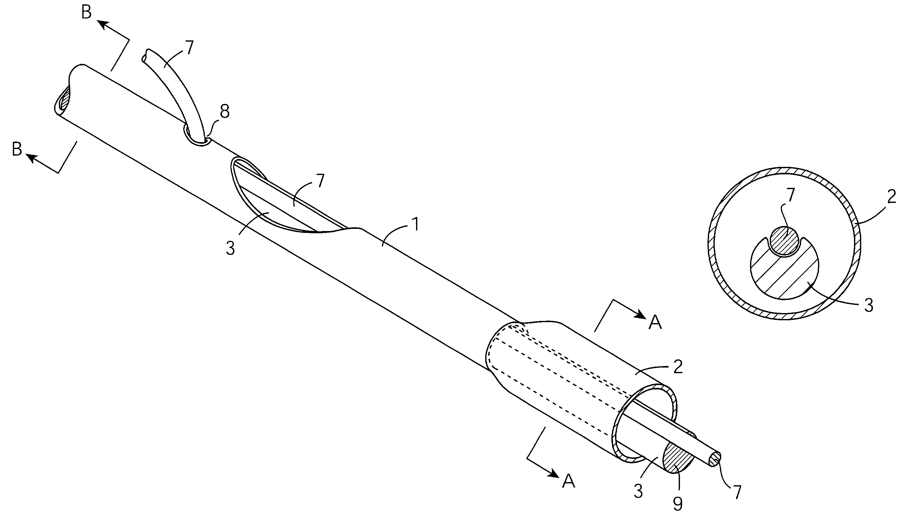
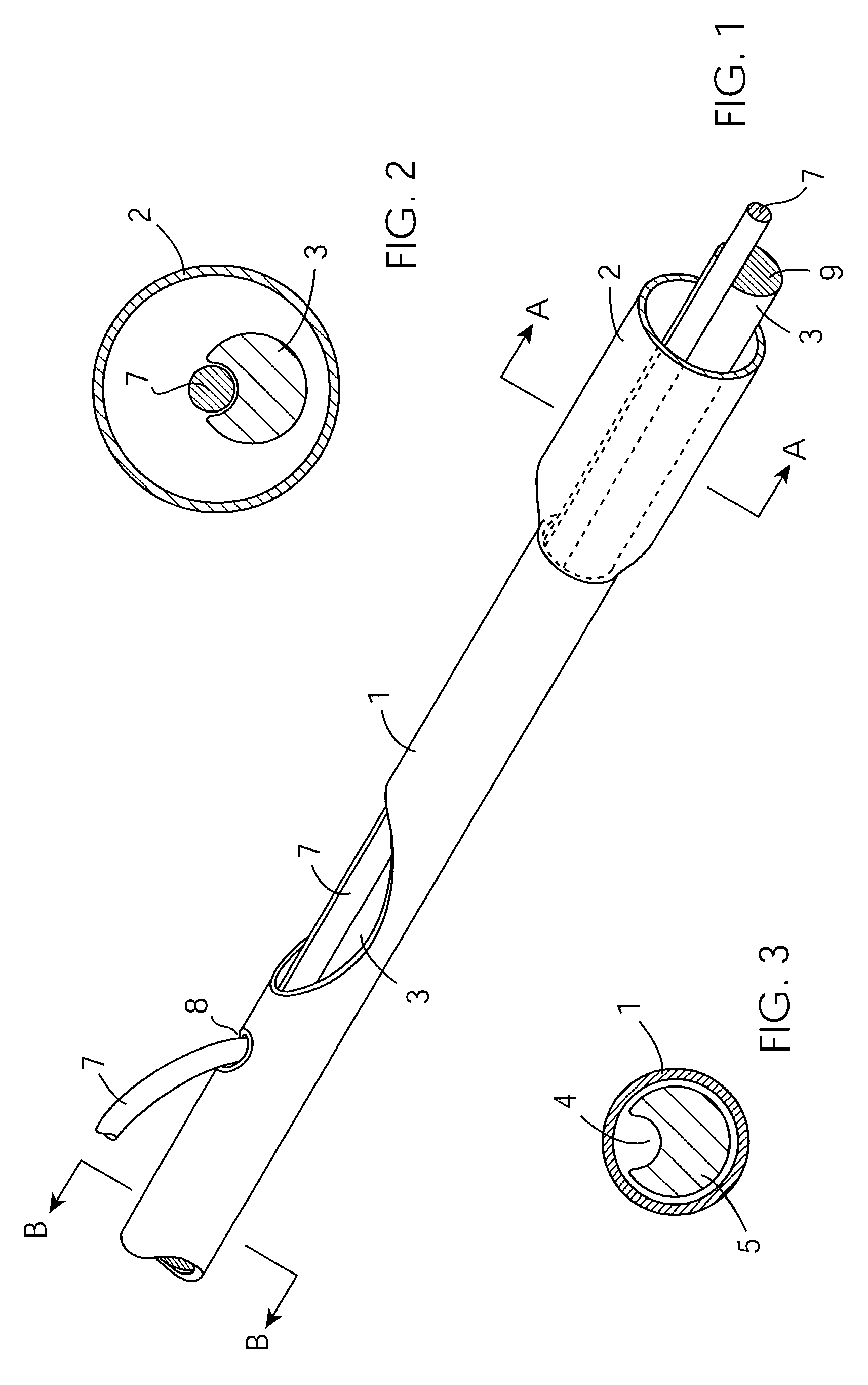
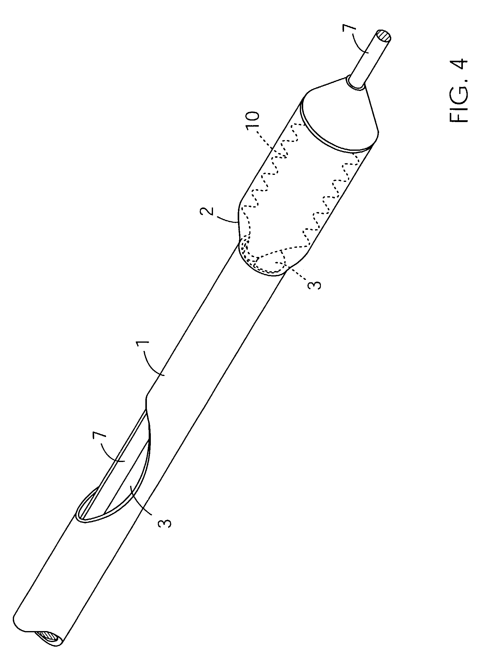
[0078]Referring to FIGS. 1 to 3 there is illustrated a catheter suitable for the delivery of a medical device such as a stent or a filter. The catheter has an outer shaft 1 with a distal end and a proximal end. The distal end comprises a pod 2 that provides a reception space for a medical device. The catheter has an inner shaft 3 comprising a solid rod 5, a surface guidewire pathway 4 for a guidewire 7. The inner shaft defines an abutment surface 9 at its distal end. The guidewire pathway 4 extends longitudinally and is configured so as to accommodate the guidewire 7. The abutment surface 9 from the pod 2 is configured so as to engage with a medical device to achieve deployment of the medical device from the pod 2. In FIGS. 1 to 4 the catheter is shown in a deployed configuration. In this deployed configuration the distal end of the inner shaft 3 is in an advanced position relative to the pod 2. The outer shaft 1 further comprises an exit port 8 where the guidewire exits the cathete...


PUM


Abstract

A catheter for delivery or retrieval of a medical device such as a filter 10 or a stent 16 has an outer shaft 1 with a pod 2 providing a medical device reception space at the distal end. An inner shaft 3 includes a solid pod with a longitudinally extending surface pathway 4 for a guidewire 7. The inner shaft 3 defines an abutment surface 9 at its distal end for deployment of the device 10, 16. The outer shaft 1 has an exit port 8 at which the guidewire 7 exits the catheter in a rapid exchange manner.

Description

CROSS-REFERENCE TO RELATED APPLICATIONS[0001]This Application is related to, and claims the benefit of, the following patent applications, namely: Irish Patent Application No. 2001 / 0591, filed Jun. 27, 2001; and U.S. Patent Application No. 60 / 301,820, filed Jul. 2, 2001; all of which are hereby incorporated herein by reference in their entirety.FIELD OF THE INVENTION[0002]Many intravascular catheter designs require that one tube move relative to another. Typically an outer tube may provide a reception space for a medical device during delivery or retrieval. The inner tube may provide a deployment function, or a centering function. Examples of such catheters include self-expanding stent delivery systems, filter delivery systems and retrieval catheters. In all these cases mechanical forces are transmitted from one end of the tube to the other. These forces may be tensile (pull), or compressive (push). Typically when a pull force is applied to one of the tubes, a reaction push force is...

Claims


Application Information

Patent Timeline
IPC IPC(8): A61M5/178A61F2/01A61F2/06A61F2/84
CPCA61F2/013A61F2/95A61F2002/011A61F2002/9528A61F2002/018A61F2230/0006A61F2230/0067A61F2/011
Inventor BRADY, EAMONFARRELL, FERGAL
Owner SALVIAC
Why Eureka
Try Eureka