
Pulse detonation firing detuning and frequency modulated firing

a technology of detonation firing and frequency modulation, which is applied in the direction of engine starters, machines/engines, turbine/propulsion engine ignition, etc., can solve the problems of increasing the overall sound level of engine operations and undesirable additional noise, so as to increase the overall sound level of engine operations and reduce ambient noise levels

Active Publication Date: 2010-08-31
GENERAL ELECTRIC CO
View PDF2 Cites 2 Cited by
  • Summary
  • Abstract
  • Description
  • Claims
  • Application Information

AI Technical Summary

Benefits of technology

[0007]Additionally, the frequency modulation of the present invention may be used to aid in reducing the levels of ambient noise during engine operation. Specifically, often during engine operations ambient noise is created which increases the overall sound level of engine operations. In many applications, including aviation, this additional noise is undesirable due to existing noise regulations and the adverse effect it has in passenger comfort. This is especially the case during takeoff and landing operations. The present invention provides a method of active noise cancellation and control.

Problems solved by technology

Specifically, often during engine operations ambient noise is created which increases the overall sound level of engine operations.
In many applications, including aviation, this additional noise is undesirable due to existing noise regulations and the adverse effect it has in passenger comfort.

Method used


Image

  • Pulse detonation firing detuning and frequency modulated firing
  • Pulse detonation firing detuning and frequency modulated firing

Examples


Embodiment Construction

[0012]The present invention will be explained in further detail by making reference to the accompanying drawings, which do not limit the scope of the invention in any way.

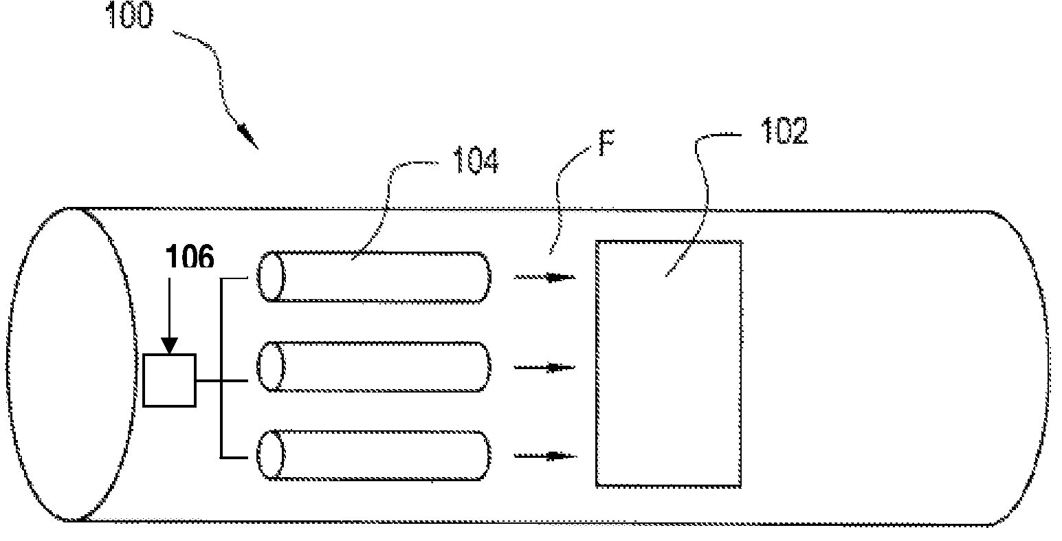
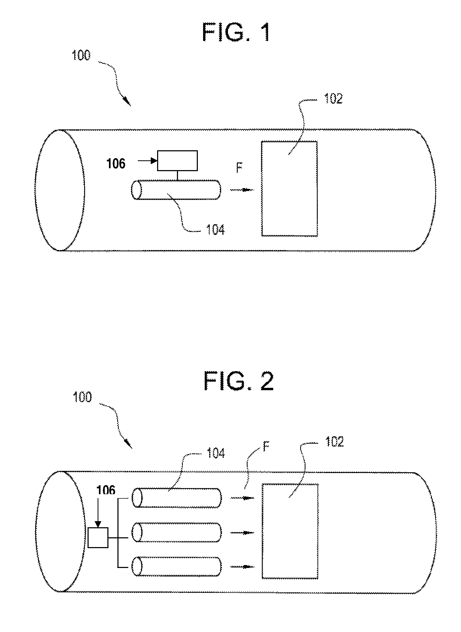
[0013]FIG. 1 is a simplified side view of an aircraft engine 100 containing a pulse detonation device 104, operated according to an embodiment of the present invention. FIG. 2 is a simplified side view of an aircraft engine 100, in accordance with another embodiment of the present invention, containing a plurality of pulse detonation devices 104, operated according to another aspect of the present invention.

[0014]Turning now to FIG. 1, an exemplary embodiment of the present invention is shown. In this embodiment an aircraft engine 100 contains a turbine section 102 and a pulse detonation device 104. The pulse detonation device is positioned upstream of the turbine section 102, so that the pulse detonation device 104 acts as a pulse detonation combustor. This configuration allows the pulse detonation device 104 to a...


PUM


Abstract

An aircraft engine is provided with at least one pulse detonation device, and the operational frequency of the pulse detonation device is varied over an operational range of frequencies around a mean frequency value. The pulse detonation device can be positioned upstream, downstream or adjacent to a turbine section of the engine. An additional embodiment of the present invention is an aircraft engine provided with more than one pulse detonation device, and the operational frequency of one, or more, of the pulse detonation devices is varied over an operational range of frequencies around a mean frequency value.

Description

BACKGROUND OF THE INVENTION[0001]This invention relates to a method and apparatus for actively varying or modulating the operating frequency of a pulsed detonation combustor in order to avoid exciting natural resonant frequencies of an engine system.[0002]In many applications, and especially in aircraft engines, excessive forced response in propulsion or power conversion equipment is avoided by resonant frequency avoidance. Namely, the driving frequency from some driving force or combustion source is purposely chosen to not coincide with a structural resonance or acoustic resonance, of the surrounding structure. In most cases, the final design of structure or hardware contains a fixed set of natural resonant frequencies. In the design process, one of the objectives is to make sure that these natural resonant frequencies do not coincide with any driving power source frequencies.[0003]In the case of reciprocating engines, axial or centrifugal flow propulsion engines and axial or centr...

Claims


Application Information

Patent Timeline
Patent Type & Authority Patents(United States)
IPC IPC(8): F02C7/22
CPCF02C5/02F02C7/264F02K1/34F02P23/04F05D2260/96F05D2260/962F05D2270/14
Inventor BADDING, BRUCE JOHNRASHEED, ADAMDEAN, ANTHONY JOHN
Owner GENERAL ELECTRIC CO
Learn More